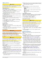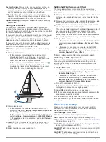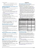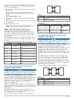
background image

The time stamp in the upper-left corner of the screen 

indicates the elapsed time since the weather data provider 

last updated the information.

Storm Cell and Lightning Information

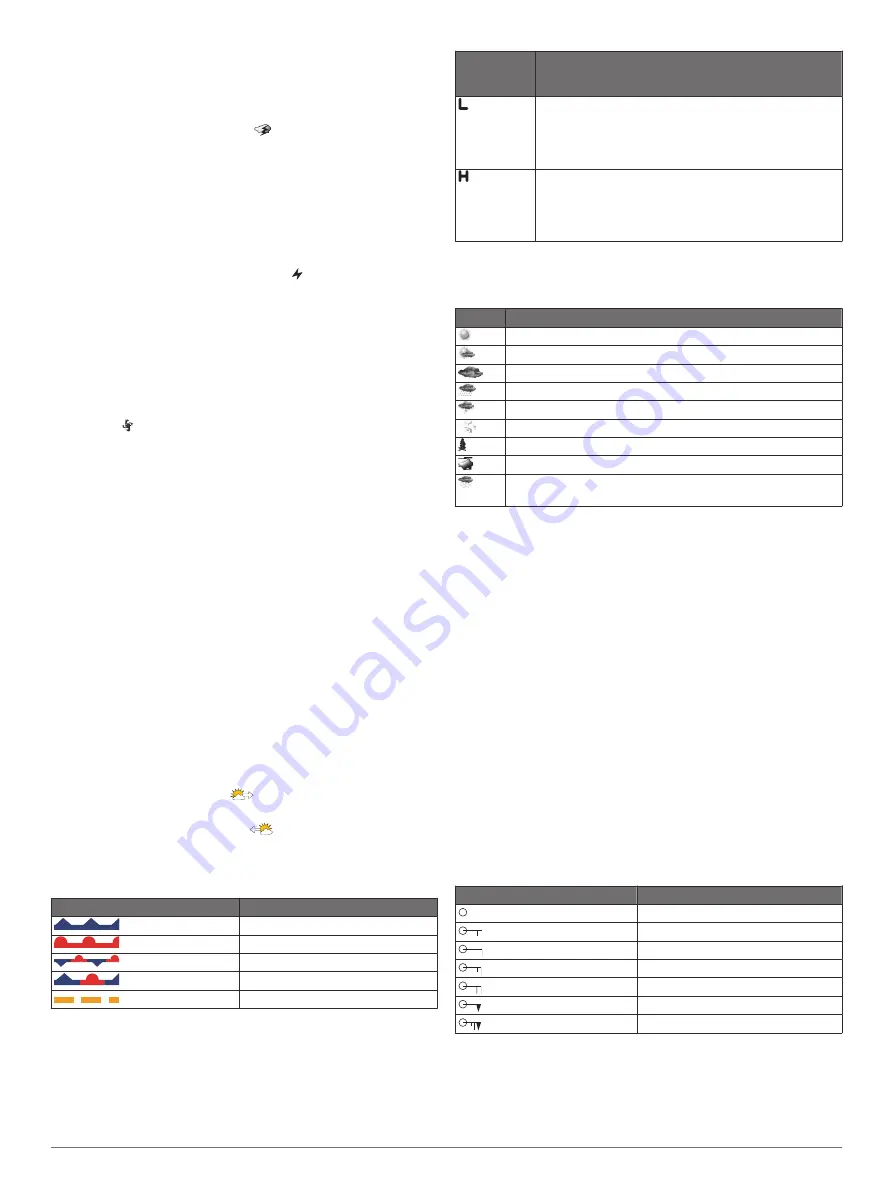
Storm cell are represented by the 

 icon on the weather 

precipitation chart. They indicate both the present position of a 

storm and the projected path of that storm in the immediate 

future.
Red cones appear with a storm cell icon, and the widest part of 

each cone points in the direction of the projected path of the 

storm cell. The red lines in each cone indicate where the storm 

will most likely be in the near future. Each line represents 15 

minutes.
Lightning strikes are represented by the   icon. Lightning 

appears on the weather precipitation chart if strikes were 

detected within the last seven minutes. The ground-based 

lightning detection network detects cloud-to-ground lightning 

only.

NOTE: 

This feature is not available on all devices and in all 

subscriptions.

Hurricane Information

The weather Precipitation chart can show the present position of 

a hurricane  , a tropical storm, or a tropical depression. A red 

line stemming from a hurricane icon indicates the projected path 

of the hurricane. Darkened dots on the red line indicate the 

projected locations through which the hurricane will pass, as 

received from the weather data provider.

Forecast Information

The Forecast chart shows city forecasts, marine forecasts, 

warnings, hurricane warnings, METARS, county warnings, 

weather fronts and pressure centers, surface pressure, and 

weather buoys.

Viewing a Marine Forecast or an Offshore Forecast

1

Select 

Charts

 > 

Forecast

.

2

Pan the chart to an offshore location.
The Marine Forecast or Offshore Forecast options appear 

when forecast information is available.

3

Select 

Marine Forecast

 or 

Offshore Forecast

.

Viewing Forecast Information for Another Time Period

1

Select 

Charts

 > 

Forecast

.

2

Select an option:
• To view the weather forecast for the next 48 hours, in 12-

hour increments, select 

 multiple times.

• To view the weather forecast for the previous 48 hours, in 

12-hour increments, select 

 multiple times.

Weather Fronts and Pressure Centers

Weather fronts appear as lines that indicate the leading edge of 

an air mass.

Front Symbol

Description

Cold front
Warm front
Stationary front
Occluded front
Trough

Pressure-center symbols often appear near weather fronts.

Pressure-
Center 
Symbol

Description

Indicates a low-pressure center, which is a region of 
relatively lower pressure. Moving away from a low-
pressure center results in increased pressure. Winds 
flow counterclockwise around low-pressure centers in 
the northern hemisphere.
Indicates a high-pressure center, which is a region of 
relatively higher pressure. Moving away from a high-
pressure center results in decreased pressure. Winds 
flow clockwise around high-pressure centers in the 
northern hemisphere.

City Forecasts

City forecasts appear as weather symbols. The forecast is 

viewed in 12-hour increments.

Symbol Weather

Fair (sunny, hot, clear)
Partly cloudy
Cloudy
Rain (drizzle, sleet, showers)
Thunderstorms
Windy
Smoke (dusty, hazy)
Foggy
Snow (snow showers, flurries, blizzard, blowing snow, sleet, 
freezing rain, freezing drizzle)

Viewing Fish Mapping Data

NOTE: 

This feature requires a GXM 54 antenna and a SiriusXM 

Fish Mapping

 service subscription.

The Fish Mapping weather chart shows information that can 

help you locate fish species.

1

Select 

Charts

 > 

Fish Mapping

.

2

If necessary, select 

Menu

 > 

Layers

, and turn on and off 

information.

Viewing Sea Conditions

The Sea Conditions feature shows information about surface 

conditions, including winds, wave height, wave period, and wave 

direction.

Select 

Charts

 > 

Sea Conditions

.

Surface Winds

Surface wind vectors appear on the Sea Conditions chart using 

wind barbs that indicate the direction from which the wind is 

blowing. A wind barb is a circle with a tail. The line or flag 

attached to the tail of the wind barb indicates the wind speed. A 

short line represents 5 knots, a long line represents 10 knots, 

and triangle represents 50 knots.

Wind Barb

Wind Speed

Calm
5 knots
10 knots
15 knots
20 knots
50 knots
65 knots

Wave Height, Wave Period, and Wave Direction

Wave heights for an area appear as variations in color. Different 

colors indicate different wave heights, as shown in the legend.

SiriusXM Weather

55

Summary of Contents for GPSMAP 87 Series

Page 1: ...GPSMAP 84XX 86XX 87XX Owner sManual...

Page 2: ...demarks of Apple Inc registered in the U S and other countries Android is a trademark of Google Inc The BLUETOOTH word mark and logos are owned by the Bluetooth SIG Inc and any use of such marks by Ga...

Page 3: ...artplotter 8 Adjusting the Wind Sensor Orientation 8 Viewing Boat Data on a Garmin Watch 8 Viewing Boat Data on a Garmin Nautix Device 9 Charts and 3D Chart Views 9 Navigation Chart and Fishing Chart...

Page 4: ...22 Linking a Boundary to a SmartMode Layout 23 Setting a Boundary Alarm 23 Disabling all Boundary Alarms 23 Deleting a Boundary 23 Deleting All Saved Waypoints Tracks Routes and Boundaries 23 Sailing...

Page 5: ...ain Clutter on the Radar Screen 39 Averaging Multiple Scans on the Radar Screen 39 Radar Options Menu 39 Radar Setup Menu 39 Reducing Cross Talk Clutter on the Radar Screen 39 Radar Appearance Setting...

Page 6: ...n for a Different Date 51 Viewing Information for a Different Tide or Current Station 51 Viewing Almanac Information from the Navigation Chart 51 Warning Manager 51 Viewing Messages 51 Sorting and Fil...

Page 7: ...ut Sentences 62 Setting the Communication Format for Each NMEA 0183 Port 62 NMEA 2000 Settings 62 Naming Devices and Sensors on the Network 62 Marine Network 62 Setting Alarms 63 Navigation Alarms 63...

Page 8: ...NMEA 2000 PGN Information 72 J1939 Information 73 NMEA 0183 Information 73 Index 74 vi Table of Contents...

Page 9: ...On Screen Buttons These on screen buttons may be displayed on some screens and functions Some buttons are accessible only in a combination page or SmartMode layout or when accessories such as a radar...

Page 10: ...hen available Press and select Power Sleep Station to set the chartplotter to standby mode when available On the home screen of some models swipe up or down on the category buttons along the right sid...

Page 11: ...until it clicks 4 Press the weather cap firmly shut to prevent corrosion Inserting a Memory Card GPSMAP 8x17 8x22 8x24 87xx NOTE The memory card reader is not included with the chartplotter It is sol...

Page 12: ...ge Customizing Pages Customizing the Layout of a SmartMode or Combination Page You can customize the layout and data shown in the combination pages and SmartMode layouts When you change the layout of...

Page 13: ...lect Edit Layout and select an option To customize the information shown when navigating select Navigation and select an option To turn on other data bars like the media controls select Top Bar or Bot...

Page 14: ...connect to the Garmin Quickdraw Contours Community update device software and plan your trip You can connect to the ActiveCaptain community for up to date feedback on marinas and other points of inter...

Page 15: ...ll the phone number back select Call Back or Dial Making Notifications Private You can turn off the pop up notifications and disable the messages list on specific chartplotters for privacy For example...

Page 16: ...en instructions Wireless Remote Control These steps are not applicable to the GRID remote input devices Pairing the GRID Device with the Chartplotter from the Chartplotter page 69 Pairing the Wireless...

Page 17: ...cording to your course and provides a visual navigation aid This view is helpful when navigating tricky shoals reefs bridges or channels and is beneficial when trying to identify entry and exit routes...

Page 18: ...ne steering to avoid land shallow water and other obstacles Premium Charts WARNING All route and navigation lines displayed on the chartplotter are only intended to provide general route guidance or t...

Page 19: ...ls If you cannot see high resolution images in your optional chart region you can select to zoom in You also can set the detail level higher by changing the map zoom detail 1 From the Navigation chart...

Page 20: ...ng and other information that is reported about a targeted AIS vessel 1 From a chart or a 3D chart view select an AIS vessel 2 Select AIS Vessel Deactivating a Target for an AIS Vessel 1 From a chart...

Page 21: ...pact the chart view From a chart select Menu Layers Adjusts the appearance of the different items on the charts Chart Layers page 13 Quickdraw Contours Turns on bottom contour drawing and allows you t...

Page 22: ...ttings You can show user data such as waypoints boundaries and tracks on the charts From a chart select Menu Layers User Data Waypoints Shows waypoints on the chart and opens the list of waypoints Bou...

Page 23: ...r a shaded relief map on the chart These differences are visible only when zoomed out too far to see the detailed charts Start Line Sets the starting line for the sailing race Setting the Starting Lin...

Page 24: ...ea 3 Select Select Download Region 4 Drag the box to select the area to download 5 Drag the corners to change the download area 6 Select Download Area The next time you connect the ActiveCaptain app t...

Page 25: ...er obstacles that may be in your path When using Go To a direct course and a corrected course may pass over land or shallow water Use visual sightings and steer to avoid land shallow water and other d...

Page 26: ...at speed and determine a safe path back to the course Stopping Navigation While navigating from an applicable chart select an option Select Menu Stop Navigation When navigating with Auto Guidance sele...

Page 27: ...Data Delete User Data Waypoints All Routes A route is a path from one location to one or more destinations Creating and Navigating a Route From Your Present Location You can create and immediately nav...

Page 28: ...ttern Select Sector Search when the location of the object is fairly known the search area is small and an intensive search is needed Select Expanding Square when the location of the object is somewha...

Page 29: ...The available values for the Shoreline Distance setting are relative not absolute To ensure the Auto Guidance line is placed the appropriate distance from shore you can assess the placement of the Aut...

Page 30: ...n option To record a track log until the track memory is full select Fill To continuously record a track log replacing the oldest track data with new data select Wrap Configuring the Recording Interva...

Page 31: ...line guidance is a visual representation of the information you need to cross the start line at the optimal time and speed After you set the starboard and port start line pins and the target speed an...

Page 32: ...keel of the boat If you want to know the true water depth and the transducer is installed below the water line measure the distance from the bottom of the transducer up to the water line NOTE This op...

Page 33: ...chart select Menu Layers My Vessel Heading Line Angle Markers 2 If necessary select Source and select an option To automatically use the available source select Auto To use the GPS antenna heading fo...

Page 34: ...your model does provide built in SideV sonar you need a compatible SideV transducer SideV scanning sonar technology shows you a picture of what lies to the sides of the boat You can use this as a sear...

Page 35: ...he boat and can be used to see a bait ball and fish Boat Range Fish Trails Bottom RealV 3D Forward Sonar View This sonar view shows a three dimensional view of what is in front of the transducer This...

Page 36: ...then connect a different transducer you should reset this option to Auto Detect Selecting a Sonar Source This feature may not be available with all models When you are using more than one sonar data...

Page 37: ...cording Record Sonar 15 minutes of sonar recording uses approximately 200 MB of space of the inserted memory card An individual recording automatically ends after it reaches 4 GB in size You can recor...

Page 38: ...etting that achieves the desired improvement should be used to remove interference from the screen Correcting installation issues that cause noise is the best way to eliminate interference Color Limit...

Page 39: ...work effectively because the sonar looks for data within the depth range of the focused area which may not include the bottom Using shift also can impact the scroll speed because data outside the dep...

Page 40: ...use the a scope to identify target returns that may be missed when the sonar data is quickly scrolling across the screen such as when your boat is moving at high speeds It can also be helpful for dete...

Page 41: ...w Offset page 35 1 From the FrontV sonar view select Menu FrontV Alarm 2 Select On 3 Enter the depth at which the alarm is triggered and select Done On the FrontV screen a depth line shows the depth a...

Page 42: ...in ClearV and SideV Transducer Installation Settings page 31 LiveScope and Perspective Appearance Settings From the LiveScope or Perspective sonar view select Menu Sonar Setup Appearance Color Scheme...

Page 43: ...w the on screen instructions Radar WARNING The marine radar transmits microwave energy that has the potential to be harmful to humans and animals Before beginning radar transmission verify that the ar...

Page 44: ...If necessary repeat for the second zone Adjusting the Radar Range The range of the radar signal indicates the length of the pulsed signal transmitted and received by the radar As the range increases...

Page 45: ...pproach and time to closest point of approach to a dangerous target Acquiring MARPA Targets Automatically You can acquire MARPA targets automatically based on MotionScope guard zones or boundaries 1 F...

Page 46: ...ls 1 From a radar screen or the radar overlay select Menu Gain 2 Select an option To adjust the gain automatically for changing conditions select Auto Low or Auto High To adjust the gain automatically...

Page 47: ...elp you avoid potential collisions find flocks of birds and track weather formations MotionScope Doppler Radar Technology page 36 This option is only available on Fantom models Pulse Exp Increases the...

Page 48: ...the autopilot feature only at a station installed next to a helm throttle and helm control device You are responsible for the safe and prudent operation of your vessel The autopilot is a tool that en...

Page 49: ...e the Shadow Drive feature before you can adjust the heading using the helm Enabling Shadow Drive page 41 With the autopilot engaged manually steer the boat The autopilot activates Shadow Drive mode W...

Page 50: ...sea and wind conditions 1 From the autopilot screen select Menu Response 2 Adjust the rudder response If you need the rudder to be more responsive and move quicker increase the value If the rudder is...

Page 51: ...Sets the length of the pattern Amplitude Sets the angle for the zigzag pattern Initial Radius Sets the radius of the spiral pattern Final Track Point Mode Sets the mode for the autopilot when it reach...

Page 52: ...e trolling motor bow offset Setting the Bow Offset page 44 Anchor Gain Sets the response of the trolling motor when in anchor lock mode If you need the trolling motor to be more responsive and move qu...

Page 53: ...istress call that information is also available and recorded with the call designates a distress call in the DSC list and marks the position of the vessel on the Navigation chart at the time of the DS...

Page 54: ...When initiating a call from the chartplotter if the radio does not have an MMSI number programmed the radio will not receive call information 1 Select Info DSC List 2 Select a vessel or a station to c...

Page 55: ...ignal strength Helm Master Select to set the Fish Point settings Helm Master Helm Master EX Select to set the trolling speed Helm Master Helm Master EX Mechanical RC Digital Electronic RC 6X6 6X7 Data...

Page 56: ...tem such as setting the type and capacity of the batteries Also displays the battery status Available on Helm Master EX systems equipped with Battery Management System BMS Calibration Calibrates vario...

Page 57: ...t Info Trip Graphs Graphs Setting the Graph Range and Time Scales You can indicate the amount of time and the range of depth that appear in the depth and water temperature graphs 1 From a graph select...

Page 58: ...e 50 Control mode Optimus control buttons Rudder Standby button You must press a mode button on the overlay bar to engage or disengage the mode When the mode is engaged the button is illuminated The o...

Page 59: ...death Yellow Hazards or unsafe practices which could result in minor personal injury or product or property damage Viewing Messages 1 Select Info Warning Manager 2 Select a message 3 Select Review Sor...

Page 60: ...nnected to the stereo and be within range of a broadcasting station For instructions on connecting an AM FM antenna see the stereo installation instructions To listen to SiriusXM radio you must have t...

Page 61: ...chartplotter to channel 0 1 Select Media Source SiriusXM 2 Tune to channel 0 The SiriusXM radio ID does not include the letters I O S or F Activating a SiriusXM Subscription 1 With the SiriusXM source...

Page 62: ...r to making safety related decisions You acknowledge and agree that you shall be solely responsible for use of the weather information and all decisions taken with respect to navigating in weather Gar...

Page 63: ...12 hour increments select multiple times Weather Fronts and Pressure Centers Weather fronts appear as lines that indicate the leading edge of an air mass Front Symbol Description Cold front Warm fron...

Page 64: ...ewing Forecast Visibility Information for Another Time Period 1 Select Charts Visibility 2 Select an option To view the visibility forecast for the next 36 hours in 12 hour increments select multiple...

Page 65: ...able features You may need to update the camera software to use this feature From the infrared video screen select Menu IR Blend Selects the infrared effect to MSX Multi Spectral Dynamic Imaging mode...

Page 66: ...a VIRB camera connect through the camera settings Connecting a VIRB Action Camera page 58 1 Set up the chartplotter s Wi Fi network Setting Up the Wi Fi Wireless Network page 8 2 Bring the camera near...

Page 67: ...Sets which lens or lenses the camera uses while shooting video Mirror Allows you to flip or mirror the video Rotation Allows you to rotate the camera angle Adding the VIRB Action Camera Controls to O...

Page 68: ...olors automatically based on the time of day Background Sets the background image Startup Image Sets the image that appears when you turn on the device Startup Layout Sets the layout that appears when...

Page 69: ...Some settings and options require additional charts or hardware Select Settings Preferences Navigation Route Labels Sets the type of labels shown with route turns on the map Turn Transition Adjusts ho...

Page 70: ...Settings Select Settings Communications NMEA 0183 Setup Port Types See Setting the Communication Format for Each NMEA 0183 Port page 62 Output Sentences See Configuring NMEA 0183 Output Sentences pag...

Page 71: ...the specified temperature Contour Sets an alarm to sound when the transducer detects a suspended target within the specified depth from the surface of the water and from the bottom Fish Fish Sets an...

Page 72: ...e capable transducer that is connected to the network 2 Measure the water temperature using a different temperature sensor or a thermometer that is known to be accurate 3 Subtract the water temperatur...

Page 73: ...aps or software updates Sharing and Managing User Data WARNING This feature allows you to import data from other devices that may have been generated by third parties Garmin makes no representations a...

Page 74: ...ActiveCaptain and Garmin Express The ActiveCaptain and Garmin Express apps help you manage your Garmin chartplotter and other devices ActiveCaptain The ActiveCaptain mobile app provides an easy to us...

Page 75: ...17Remove the memory card NOTE If the memory card is removed before the device restarts fully the update is not complete Software Updates You may need to update the software when you install a new dev...

Page 76: ...tter to a computer to see the computer screen on the chartplotter touchscreen and control the computer using the chartplotter touchscreen To see the computer screen you must connect the computer to th...

Page 77: ...g The device is coated with a special anti reflective coating which is very sensitive to waxes and abrasive cleaners 1 Apply an eyeglass lens cleaner specified as safe for anti reflective coatings to...

Page 78: ...when the original waypoint was created If the original waypoint was taken from a map there should be a legend on the map that lists the map datum and position format used to create that map Most often...

Page 79: ...r rating IEC 60529 IPX7 The device withstands incidental exposure to water of up to 1 m for up to 30 min For more information go to www garmin com waterrating Fuse 15 A Input voltage From 10 to 35 Vdc...

Page 80: ...up to 30 min For more information go to www garmin com waterrating Sonar Models Specifications Specification Measurement Sonar frequen cies2 Traditional 50 200 77 200 83 200 kHz Single Channel CHIRP...

Page 81: ...igation based vehicle speed 65256 517 Engine fuel temperature 1 65262 174 Engine oil temperature 1 65262 175 Engine fuel delivery pressure 65263 94 Engine oil pressure 65263 100 Description PGN SPN En...

Page 82: ...ourses 17 current stations 50 51 indicators 11 D DAB 52 53 data backup 66 copying 65 management 65 deleting all user data 23 depth log 49 depth shading 13 14 destinations navigation chart 18 selecting...

Page 83: ...65 Route To 17 routes 17 19 22 copying 65 creating 19 20 deleting 20 editing 19 navigating 19 navigating parallel to 20 viewing list of 19 waypoints 65 S safe depth 61 safe height 61 safe zone collis...

Page 84: ...ating 10 18 deleting 19 editing 18 man overboard 18 navigating to 19 projecting 18 showing 14 sonar 28 tracked vessel 45 46 viewing list of 18 weather 54 55 alarms 63 broadcasts 54 charts 15 54 fishin...

Page 85: ......

Page 86: ...support garmin com GUID 25CCEC48 337E 47C0 8B89 5C35CCDB65AC v17 March 2021...

Reviews: