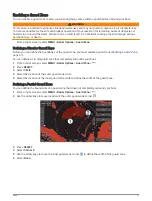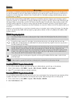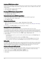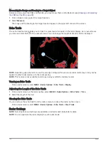
Radar Overlay and Chart Data Alignment
When using the Radar overlay, the chartplotter aligns radar data with chart data based on the boat heading,
which is based by default on data from a magnetic heading sensor connected using a NMEA 0183 or NMEA
2000 network. If a heading sensor is not available, the boat heading is based on GPS tracking data.
GPS tracking data indicates the direction in which the boat is moving, not the direction in which the boat
is pointing. If the boat is drifting backward or sideways due to a current or wind, the Radar overlay may
not perfectly align with the chart data. This situation should be avoided by using boat-heading data from an
electronic compass.
If the boat heading is based on data from a magnetic heading sensor or an automatic pilot, the heading data
could be compromised due to incorrect setup, mechanical malfunction, magnetic interference, or other factors.
If the heading data is compromised, the Radar overlay may not align perfectly with the chart data.
Transmitting Radar Signals
NOTE: As a safety feature, the radar enters standby mode after it warms up. This gives you an opportunity to
verify the area around the radar is clear before beginning radar transmission.
1 With the chartplotter off, connect your radar as described in the radar installation instructions.
2 Turn on the chartplotter.
If necessary, the radar warms up and a countdown alerts you when the radar is ready.
3 Select Radar.
4 Select a radar mode.
A countdown message appears while the radar is starting up.
5 Select MENU > Transmit Radar.
Stopping the Transmission of Radar Signals
From a radar screen, select MENU > Radar To Standby.
TIP: Press > Radar To Standby from any screen to quickly stop radar transmission.
Setting Up the Timed Transmit Mode
To help conserve power, you can set up time intervals in which the radar will transmit and not transmit (standby)
signal transmissions.
NOTE: This feature is not available in dual radar modes.
1 From a radar screen, select MENU > Radar Options > Timed Transmit.
2 Select Timed Transmit to enable the option.
3 Select Stdby Time, enter the time interval between radar signal transmissions, and select Done.
4 Select Transmit Time, enter the duration of each radar signal transmission, and select Done.
Enabling and Adjusting a Radar No Transmit Zone
You can indicate areas within which the radar scanner does not transmit signals.
NOTE: GMR Fantom and xHD2 radar models support two no-transmit zones. Most other GMR radar models
support one no-transmit zone. GMR 18 HD+ radar models do not support no-transmit zones.
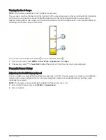
1 From a radar screen, select MENU > Radar Setup > Installation > No Transmit Zone.
The no-transmit zone is indicated by a shaded area on the radar screen.
2 Select Angle 1, and select the new location for the first angle.
3 Select Angle 2, and select the new location for the second angle.
4 Select Done.
5 If necessary, repeat for the second zone.
Radar
95
Summary of Contents for GPSMAP1222
Page 1: ...GPSMAP 10X2 12X2SERIES Owner sManual...
Page 14: ......
Page 213: ......
Page 214: ...support garmin com GUID C3CEA164 A1CB 4B15 92F2 5C04944CC6F3 v21 January 2024...

