background image

190-00303-A3

October, 2020

Revision 3

GSB 15 

USB Database and 

Charging Hub 

Installation Manual

Summary of Contents for GSB 15

Page 1: ...190 00303 A3 October 2020 Revision 3 GSB 15 USB Database and Charging Hub Installation Manual ...

Page 2: ...y of this manual or of any revision hereto provided that such electronic or printed copy of this manual or revision must contain the complete text of this copyright notice and provided further that any unauthorized commercial distribution of this manual or any revision hereto is strictly prohibited Garmin International Inc 1200 E 151st Street Olathe KS 66062 USA www garmin com Garmin Europe Ltd Li...

Page 3: ...omponents contain chemicals known to the State of California to cause cancer birth defects or reproductive harm This Notice is being provided in accordance with California s Proposition 65 If you have any questions or would like additional information please refer to our web site at http www garmin com prop65 Revision Page Number Section Number Description of Change 3 1 2 1 3 1 4 1 2 1 1 2 2 1 2 3...

Page 4: ...merica copyright laws and international copyright treaties You further acknowledge that the structure organization and code of the Software are valuable trade secrets of Garmin and or its third party providers and that the Software in source code form remains a valuable trade secret of Garmin and or its third party providers You agree not to reproduce decompile disassemble modify reverse assemble ...

Page 5: ...igurations 2 1 2 4 Special Tools Required 2 1 2 5 Cabling and Wiring 2 2 2 6 Shielding and Electrical Bonding Considerations 2 2 2 7 Cooling Requirements or Considerations 2 2 2 8 Mounting Requirements 2 3 Section 3 Installation Procedure 3 1 3 1 Wiring Harness Installation 3 1 3 2 Equipment Mounting 3 1 3 3 Decorative Cover Installation 3 2 Section 4 Post Installation Configuration Checkout 4 1 4...

Page 6: ...s manual assumes use by competent and qualified avionics engineering personnel and or avionics installation specialist using standard maintenance practices in accordance with Title 14 of the Code of Federal Regulation and other relevant accepted practices This manual is not intended for use by individuals who do not possess the competencies and abilities set forth above NOTE Garmin recommends inst...

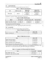
Page 7: ...10 02201 10 GSB 15 side power input 2 011 04937 01 010 02201 01 010 02201 11 1 Includes connector kit 011 05044 00 2 Referred to as rear and side respectively throughout this document Table 1 3 Required Accessories Item Garmin P N GSB 15 Connector Kit 011 05044 00 Table 1 4 Optional Accessories Item Garmin P N GSB 15 2 25 Mounting Kit 011 05043 00 GSB 15 3 125 Mounting Kit 011 05043 01 GSB 15 Deco...

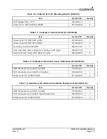
Page 8: ... 00117 01 1 Conn Hsg Rcpt 3mm P Single Row Locking 6 CKT Nylon 330 00771 05 1 Contact Female Crimp 20 24 AWG 15u Gold 336 00065 05 6 Table 1 8 Contents of Decorative Cover Unfinished 011 05291 00 Item Garmin P N Quantity SMP Decorative Cover GSB 15 w VHB 115 03439 01 1 DCP Decorative Cover GSB 15 Unfinished 125 00627 02 1 Screw 4 40x 312 FLHP100 SS P 211 63204 09 2 Table 1 9 Contents of Decorative...

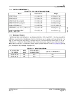
Page 9: ...dvisory information on the Garmin Dealer Resource web site at www garmin com using their Garmin provided user name and password Table 1 10 Unit and Accessory Weights Model Part Number Weight GSB 15 Rear 011 04937 00 0 16 lbs 0 07 kg GSB 15 Side 011 04937 01 0 16 lbs 0 07 kg GSB 15 2 25 Mounting Kit 011 05043 00 0 11 lbs 0 05 kg GSB 15 3 125 Mounting Kit 011 05043 01 0 20 lbs 0 09 kg GSB 15 Connect...

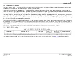
Page 10: ...egrated non TSO functions TSO articles and any accepted integrated non TSO function s must have separate approval for installation in an aircraft The article may be installed only according to 14 CFR part 43 or the applicable airworthiness requirements In accordance with the Bilateral Oversight Board Decision 006 for the Agreement Between the United States of America and the European Union on Coop...

Page 11: ...e GSB 15 contains no software or airborne electronic hardware with related design assurance levels The GSB 15 COTS module provides no design assurance for pass through data Those installing this article with other articles utilizing pass through data must determine means for detecting misleading or corrupt data 1 3 6 Database For information on certification compliance for databases refer to Garmi...

Page 12: ...3 Power Specifications Maximum power while charging both ports 18W each and backlight enabled 40W 28V 1 43A 14V 2 86A Maximum power with no devices connected 500mW 28V 17mA 14V 35mA 1 5 4 Over Temperature Protection The GSB 15 is equipped with over temperature detection and may re negotiate to 5V 1 5A MAX output current Once the device has cooled normal output current will resume Table 1 14 Genera...

Page 13: ...he backlight The backlight brightness is calibrated for night time use and may not be visible in daylight conditions It is acceptable and preferred to install only the pins that are needed CAUTION Do not apply power to the unit until after the rear connector is completely seated Connecting the unit while power is applied may cause damage to the device and to other LRUs that are connected to the da...

Page 14: ... installation Circuit breaker 2 3 Installation Configurations The GSB 15 can be installed in either a rear connector or side connector configuration Refer to the outline and installation drawings in Appendix A Optional 2 25 and 3 125 mounting kits are also available see Table 1 3 to mount the GSB 15 in existing instrument panel holes NOTE At least 2 of the 4 provided mounting holes must be used di...

Page 15: ...following documents for applicable bonding techniques AC 43 13 1B CHG 1 Acceptable Methods Techniques and Practices Aircraft Inspection and Repair Chapter 11 Aircraft Electrical Systems SAE ARP 1870A Aerospace Systems Electrical Bonding and Grounding for Electromagnetic Compatibility and Safety A bonding procedure developed and supplied by the aircraft manufacturer if available The electrical bond...

Page 16: ...5 UNIT 235 00117 00 MOUNTING SCREWS CRIMP PIN 336 00065 05 6 PLACES CONNECTOR KIT GSB 15 011 05044 00 6 PLACES 336 00065 05 011 04937 01 GSB 15 UNIT PANEL AIRCRAFT 2 PLACES 211 60304 08 235 00117 00 16 22 AWG RING TERMINAL 330 00771 05 CRIMP PIN HOUSING 4 40 x 25 6 4 PHP MOUNTING SCREWS CRIMP PIN 4 40 x 125 PAN HEAD SCREW 211 60234 04 REAR CONNECTOR 00 CONFIG WITH 2 25 MOUNTING KIT 011 05043 00 RE...

Page 17: ...ings shown in Appendix A of this manual 1 Assemble connector per instructions in Section 2 2 Install the unit from the back side of the desired installation surface with the circular surface protruding through the hole 3 Attach the unit to the installation surface using a minimum of two screws oriented diagonally Rotational orientation of the unit within the mounting location is at the installer s...

Page 18: ...he two provided screws 3 Peel off the tape liners from the Intermediate Piece 4 Install the Cosmetic Piece NOTE For best results install the Decorative Cover as specified below Recommended installation temperature 70 100 F 21 38 C Minimum installation temperature 50 F 10 C Recommended screw torque 4 6 lbf in After removing the tape liners from the Intermediate Piece Step 3 above avoid touching the...

Page 19: ...d for proper connections to the aircraft systems and other avionics equipment Point to Point continuity must be checked to expose any faults such as shorting to ground or wiring discrepancies Any faults or discrepancies must be corrected before proceeding After accomplishing a continuity check perform power and ground checks to verify proper power distribution to the GSB 15 Any faults or discrepan...

Page 20: ...190 00303 A3 GSB 15 Installation Manual Rev 3 Page 5 1 5 CONTINUED AIRWORTHINESS Maintenance of the GSB 15 is on condition only ...

Page 21: ...gure 6 1 Unit View of P201 P202 Table 6 1 J201 J202 Connector Pin Pin Name I O COMMENTS 1 AIRCRAFT POWER IN 14V 28V Aircraft Power Input 2 USB DN I O May use shielded CAT 5 ethernet cable 3 USB DP I O May use shielded CAT 5 ethernet cable 4 USB GND May use shielded CAT 5 ethernet cable 5 BACKLIGHT ENABLE IN Deactivated Low configuration strap Do not connect for backlight ON Ground connection for b...

Page 22: ... 005 11 11 0 13 BACK OF MOUNTING SUFACE 47 0 16 2 64 1 85 80 20 24 1 50 38 1 1 50 38 1 92 23 5 4 10 BACK OF MOUNTING SURFACE 1 02 25 9 84 21 4 4 10 1 50 38 1 1 55 39 3 REAR CONNECTOR 00 CONFIG WITH CONNECTOR KIT 011 05044 00 SIDE CONNECTOR 01 CONFIG UNIT ONLY REAR CONNECTOR 00 CONFIG UNIT ONLY 2 DIMENSIONS ARE NOMINAL AND TOLERANCES ARE NOT IMPLIED UNLESS SPECIFICALLY STATED NOTES DIMENSIONS INCHE...

Page 23: ...s Qty 2 o N 5 9 7 3 1 3 6 7 4 8 1 3 8 8 1 5 2 1 CONNECTOR KIT GSB 15 011 05044 00 AIRCRAFT PANEL 211 60304 08 4 40 x 25 6 4 PHP 2 PLACES 011 04937 00 211 60234 04 4 40 x 125 PAN HEAD SCREW 330 00771 05 CRIMP PIN HOUSING 16 22 AWG RING TERMINAL GSB 15 UNIT 235 00117 00 MOUNTING SCREWS CRIMP PIN 336 00065 05 6 PLACES CONNECTOR KIT GSB 15 011 05044 00 6 PLACES 336 00065 05 011 04937 01 GSB 15 UNIT PA...

Page 24: ...s 45 0 0 00 0 0 00 438 005 11 11 0 13 438 005 11 11 0 13 438 005 11 11 0 13 438 005 11 11 0 13 OR RECOMMENDED PANEL CUTOUT DIMENSIONS FOR UNIT R O R O FOR PAN HEAD SCREWS STANDARD HOLES COUNTERSUNK HOLES FOR 100 FLAT HEAD SCREWS OR 129 003 2X 3 26 0 08 1 000 030 005 25 40 0 76 0 13 2X 129 003 3 26 0 08 THRU 225 5 72 X 100 ...

Page 25: ...35 Minimum 125 188 3 18 4 76 313 7 95 Minimum Panel Thickness Recommended Screw Length 000 050 0 00 1 27 188 4 76 Minimum 050 125 1 27 3 18 250 6 35 Minimum 125 188 3 18 4 76 313 7 95 Minimum 6 32 4 PLACES 125 00581 02 ADAPTER PLATE Ø 2 25 2 NOMINAL 2 PLACES 211 63304 08 011 05043 00 MOUNTING KIT 2 25 GSB 15 PANEL AIRCRAFT 4 40 x 25 6 4 FLHP100 MOUNTING SCREWS MOUNTING SCREWS GSB 15 UNIT 011 04937...

Page 26: ...50 003 4X 3 80 0 08 2 625 66 68 1 856 47 15 1 856 47 15 0 76 0 13 57 15 2 250 030 005 1 313 33 34 011 05043 00 STANDARD HOLES FOR PAN HEAD SCREWS RECOMMENDED PANEL CUTOUT DIMENSIONS FOR UNIT WITH MOUNTING KIT 011 05043 01 STANDARD HOLES FOR PAN HEAD SCREWS 150 003 4X 3 80 0 08 3 500 88 90 2 475 62 86 2 475 62 86 0 76 0 13 79 38 3 125 030 005 1 750 44 45 ...

Page 27: ...Flat Head Screws 011 05043 00 and 01 Mounting Kits 011 05043 00 COUNTERSUNK HOLES FOR 100 FLAT HEAD SCREWS RECOMMENDED PANEL CUTOUT DIMENSIONS FOR UNIT WITH MOUNTING KIT 011 05043 01 COUNTERSUNK HOLES FOR 100 FLAT HEAD SCREWS 4X 150 3 80 THRU ALL 279 7 09 X 100 4X 150 3 80 THRU ALL 279 7 09 X 100 ...

Page 28: ... 15 011 05291 0X COSMETIC PIECE IS AVAILABLE IN TWO FINISHES PART NUMBER FINISH 011 05291 00 CHROMATE CONVERSION COATING UNFINISHED 011 05291 01 BLACK POWDER COAT COSMETIC PIECE WILL MOUNT FLUSH WITH UNIT ON A 08 2 0 THICK PANEL RECOMMENDED PANEL CUTOUT DIMENSIONS FOR UNIT WITH DECORATIVE COVER GSB 15 UNIT 011 04937 01 2 PLACES 211 63204 09 125 00627 0X COSMETIC PIECE 4 40 x 31 7 9 FLHP100 115 034...

Page 29: ...OUT TEMPLATE FOR GSB 15 INSTALLATION SCALE 1 1 MOUNTING SCREWS NEW INSTALLATIONS WITH 2 COVER NEW INSTALLATIONS WITH DECORATIVE COVER OR ADDING A DECORATIVE NEW INSTALLATIONS WITH 4 MOUNTING SCREWS IMPORTANT Ensure the Page Scaling setting is set to NONE when printing this page Verify dimensions Page A 3 or A 7 of printed template are accurate before cutting panel ...

Page 30: ...WIRES 25 ft MAX 2 USE CAT 5 SHIELDED TWISTED PAIR WIRING 6 ft MAX 3 CONNECT TO CAT 5 SHIELD USING M83519 SOLDER SLEEVE OR EQUIVALENT 1 2 54 cm MAX FROM CONNECTOR SOLDER SLEEVES WITH PRE INSTALLED LEADS ARE ACCEPTABLE 4 TERMINATE CAT 5 SHIELD TO THE BACK OF THE GSB 15 USING THE RING TERMINAL AND RING TERMINAL SCREW P N 235 00117 00 AND 211 60234 04 5 SYMBOL DESIGNATIONS SEE NOTE 4 5A SEE NOTE 1 SEE...

Page 31: ......

Reviews: