190-01639-00
GSU 75 ADAHRS Installation Manual
Rev. 6
Page 3-5
the sensor through a metal doubler connected with rivets. Another type of fastener that
allows for a path to the conductive part of the airframe may also be used.
2. Install OAT sensor –After the surfaces have been prepared; place the ring terminal (item 2) over
the end of the sensor (item 4). Insert the sensor and ring terminal into the hole in the skin of the
aircraft. Place the washer (item 6) over the end of the sensor on the outside of the aircraft. Thread
the nut (item 5) onto the sensor. Using a deep well socket and torque wrench, along with a 9/16”
open end wrench to hold the body of the sensor, tighten to 100 inch-pounds ± 20 inch-pounds.
3. Route cable–Run the 3-conductor cable (item 3) through the airframe to the location of the GSU
75.
4. Strip jacket and shield–Cut the 3-conductor cable (item 3) to the required length. Strip back 2.0” to
3.5” of jacket while retaining the shield on the 3-conductor cable (item 3). Trim away enough to
leave 0.5” of shield exposed.
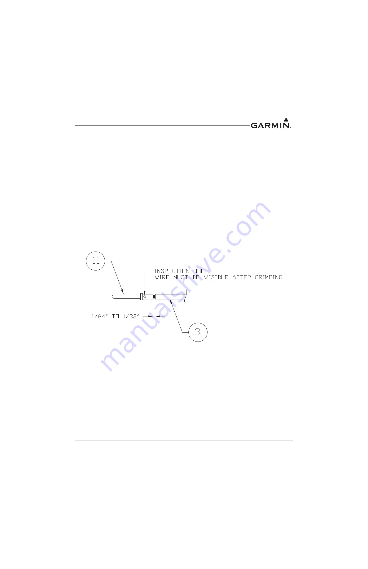
5. Install pins onto cable. Strip back approximately 0.17 inches of insulation from each wire of the 3-
conductor cable (item 3) and crimp a pin/socket (item 11) to each conductor. It is the responsibility
of the installer to determine the proper length of insulation to be removed. Wire must be visible in
the inspection hole after crimping and the insulation must be 1/64 – 1/32 inches from the end of
the contact as shown in Figure 3-1.
Figure 3-1 Insulation to Pin/Socket Clearance
6. Connect 16 AWG pigtail wire (item 8)–Cut a 16 AWG (item 8) wire to 3” long. Strip back 0.5” of
insulation from this wire. Connect the shield of the 3-conductor cable (item 3) to the pigtail wire
(item 8) using an approved shield termination technique. The guidance of FAA advisory circular
AC 43.13 may be a helpful reference for this procedure.
a) Slide a solder sleeve (item 1) onto the prepared wire assembly (items 3 and 8) and shrink
using the heat gun. The chosen size of solder sleeve must accommodate the number of
conductors present in the cable. For this application, the solder sleeve that best fits the
3- conductor cable (item 3) and the 16 AWG pigtail wire (item 8) is M83519/1-4.
340095
The document reference is online, please check the correspondence between the online documentation and the printed version.


