GTN 625/635/650 TSO Installation Manual
190-01004-02
Page 6-14
Rev. F
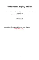
6.6.6.1 Photocell Configuration Page
Access the Photocell Configuration page, as shown
in Figure 6-10 by touching the ‘Configure
Photocell’ key from the Lighting Configuration
page. The following parameters can be configured
by touching the corresponding key. Each selection
displays a numeric keypad where the numeric
values can be entered.
RESPONSE TIME
Sets the speed with which the brightness responds
to the input level (bus voltage or ambient light)
changes. The higher the number the slower the
display responds. This field has a range of 2-7 seconds, and is set to 2 seconds as a default value.
SLOPE
Sets the sensitivity the brightness of the display has to changes in the input level. The higher the number,
the brighter the display for a given increase in the input level. This field has a range of 0-100, and is set to
50 as the default setting.
OFFSET
Adjusts the lighting level up or down for any given input level. This field has a range of 0 (zero) to 99, and
is set to 50. At 50, there is no offset. This may also be used to match lighting curves with other equipment
in the panel.
KEY BACKLIGHT CUTOFF
This parameter configures the point at which key backlighting is switched off in bright light. For example,
a value of 70% means that the key backlights will be off at photocell source input levels above 70%. This
field has a range of 0 (zero) to 100% and is set to 80% as the default setting.
PHOTOCELL TRANSITION
When a lighting bus is used to control the lighting of the display, this parameter sets the point on the
lighting bus control below which the display brightness tracks the GTN’s photocell. This field has a range
of 5 to 50, and is set to 25 as the default setting.
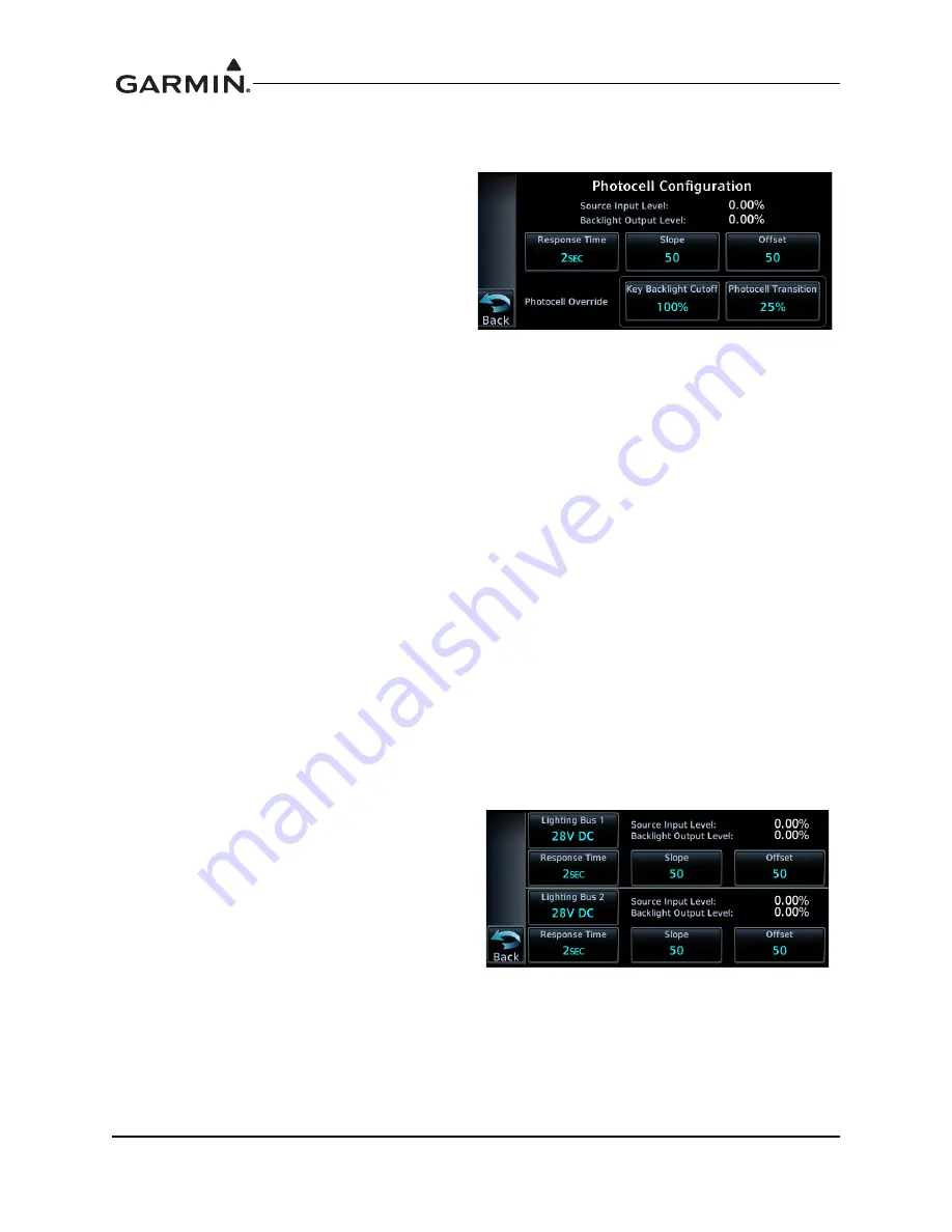
6.6.6.2 Lighting Bus Configuration Page
The Lighting Bus Configuration page offers the
same Response Time, Slope, and Offset
adjustments as described in Section 6.6.6.1.
LIGHTING BUS SOURCE
To configure the lighting bus source voltage, touch
the ‘Lighting Bus 1’ or ‘Lighting Bus 2’ key. Select
14V DC, 28V DC, 5V DC, or 5V AC depending on
the lighting bus voltage source.
Figure 6-10. Photocell Configuration Page
Figure 6-11. Lighting Bus Configuration Page
Summary of Contents for GTN 625
Page 1: ...190 01004 02 February 2013 Revision F GTN 625 635 650 TSO Installation Manual ...
Page 2: ......
Page 242: ...GTN 625 635 650 TSO Installation Manual 190 01004 02 Page D 36 Rev F Figure D 24 Reserved ...
Page 250: ...GTN 625 635 650 TSO Installation Manual 190 01004 02 Page D 44 Rev F Figure D 32 Reserved ...
Page 253: ......
Page 254: ......