


GTN 625/635/650 TSO Installation Manual
190-01004-02
Page 5-10
Rev. F
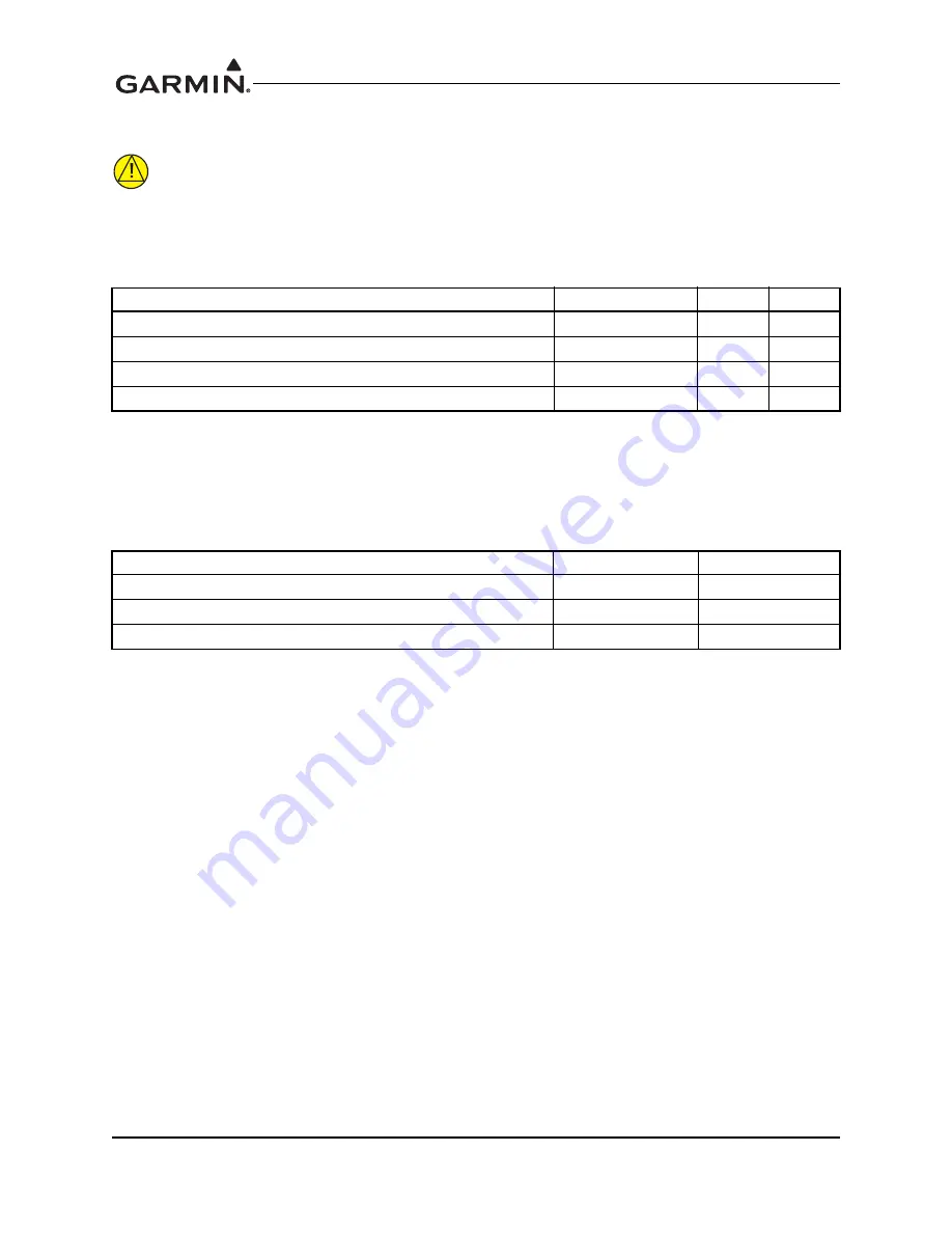
5.2.2 Lighting Bus
CAUTION
Connection of the lighting bus to incorrect pins can cause damage to the unit that will
require return to the factory for repair. Ensure that the lighting bus is connected to the
correct pins and does not short to any adjacent pins prior to applying power to the unit,
including the lighting bus.
The GTN can be configured to track 28 VDC, 14 VDC, 5 VDC or 5 VAC lighting buses using these inputs.
Two lighting buses allow for independent control of display and bezel lighting. Alternatively, the GTN can
automatically adjust for ambient lighting conditions based on the photocell. Refer to Section 6.6.6 for
instructions on configuring the lighting inputs.
5.2.3 Antennas
The GPS/SBAS antenna use a TNC coaxial connector on the connector backplate. The COM and NAV
antennas use BNC coaxial connectors on the connector backplate. Reference Figure D-5 for splitter/
diplexer block diagrams.
Pin Name
Connector
Pin
I/O
LIGHTING BUS 1 HI
P1001
18
In
LIGHTING BUS 1 LO
P1001
17
In
LIGHTING BUS 2 HI
P1001
61
In
LIGHTING BUS 2 LO
P1001
42
In
Pin Name
Connector
I/O
GPS/SBAS ANTENNA
P1006
In
COM ANTENNA
P1007
I/O
NAV ANTENNA
P1008
In
Summary of Contents for GTN 625
Page 1: ...190 01004 02 February 2013 Revision F GTN 625 635 650 TSO Installation Manual ...
Page 2: ......
Page 242: ...GTN 625 635 650 TSO Installation Manual 190 01004 02 Page D 36 Rev F Figure D 24 Reserved ...
Page 250: ...GTN 625 635 650 TSO Installation Manual 190 01004 02 Page D 44 Rev F Figure D 32 Reserved ...
Page 253: ......
Page 254: ......


