Page 5-20
GTN 725/750 TSO Installation Manual
Rev. A
190-01007-02
5.5.7
GAD 42 Interface Check
This check verifies that the GTN is interfaced with the GAD 42.
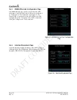
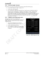
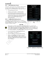
Go to the GAD 42 Configuration Page from the External
Systems page. Touch ‘External Systems’, then touch ‘GAD 42’.
1.
Verify that Status is ACTIVE.
2.
Change any of the options to a different number.
3.
Verify that after changing one of the options the
STATUS field changes to SENDING then changes back
to ACTIVE. If the entry reverts to the previous number
when ACTIVE is displayed, then refer to the latest
revision of the GAD 42 Installation Manual
(P/N 190-00159-00).
5.5.8
Lighting Bus Interface Check
The display and key backlighting on the GTN can track an
external lighting/dimmer bus input and use it to vary the display
and key backlight levels accordingly. This check verifies that the
interface is connected correctly.
CAUTION
When 14 VDC or 28 VDC lighting buses are connected to the GTN, connection of the
aircraft lighting bus to the incorrect input pins can cause damage to the GTN. Always start
this test with the dimming bus at the lowest setting, and slowly increase the brightness. If it
is noticed that the LIGHTING level displayed on the GTN does not increase as the lighting
is increased in brightness, verify that the wiring is correct before proceeding.
1.
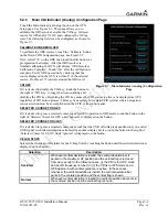
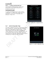
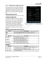
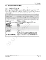
Go to the Lighting Bus Configuration page from the
GTN Setup page. See Figure 5-21.
2.
Ensure the lighting bus is set to its minimum setting.
3.
Slowly vary the lighting bus level that is connected to
the GTN. Verify that the Source Input Level value
displayed on the configuration screen tracks the lighting
bus setting. Continue to maximum brightness and verify
proper operation.
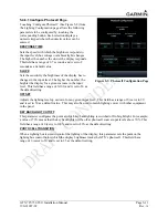
Figure 5-20. GAD 42 Configuration
Page
Figure 5-21. Lighting Bus Configuration Page
Summary of Contents for GTN 725
Page 1: ...190 01007 02 TBD 2010 Rev A GTN 725 750 TSO Installation Manual GTN 725 and GTN 750...
Page 2: ......
Page 177: ......
Page 178: ......

