background image

Playing Sonar Recordings

Before you can play back the sonar recordings, you must 

download and install the HomePort

 application and record 

sonar data onto a memory card.

1

Remove the memory card from the device.

2

Insert the memory card into a card reader attached to a 

computer.

3

Open the HomePort application.

4

Select a sonar recording from your device list.

5

Right-click the sonar recording in the lower pane.

6

Select 

Playback

.

Radar

 WARNING

The marine radar transmits microwave energy that has the 

potential to be harmful to humans and animals. Before 

beginning radar transmission, verify that the area around the 

radar is clear. The radar transmits a beam approximately 12° 

above and below a line extending horizontally from the center of 

the radar.
When the radar is transmitting, do not look directly at the 

antenna at close range; eyes are the most sensitive part of the 

body to electromagnetic energy.

NOTE: 

Not all models support radar.

When you connect your compatible chartplotter to an optional 

Garmin marine radar, such as a GMR

 1226 xHD2 or a GMR 24 

HD, you can view more information about your surroundings.
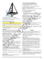
The GMR transmits a narrow beam of microwave energy as it 

rotates to a 360° pattern. When the transmitted energy contacts 

a target, some of that energy is reflected back to the radar.

Radar Display Modes

NOTE: 

Not all modes are available with all radar devices and all 

chartplotters.
Select Radar.

Cruising Mode

: Shows a full-screen image of the gathered 

radar information.

Harbor Mode

: Intended for use in inland waters, this mode 

works best with short-range signals (2 nm or less).

Offshore Mode

: Intended for use in open waters, this mode 

works best with long-range signals.

Sentry Mode

: Allows you to put the radar into timed-transmit 

mode, in which you can configure a radar transmit and 

standby cycle to conserve power. You can also enable a 

guard zone in this mode, which identifies a safe zone around 

your boat. If you switch from Sentry mode to another mode, 

the radar switches to full-time transmission and disables all 

guard zones.

Radar Overlay Mode

: Shows a full-screen image of the 

gathered radar information on top of the Navigation chart. 

The Radar overlay displays data based on the most recently 

used radar mode.

Dual Range Mode

: Provides a side-by-side view of both short-

range and long-range radar data.

Changing the Radar Mode

1

From a combination screen or SmartMode layout with radar, 

select 

Menu

 > 

Radar Menu

 > 

Change Radar

.

2

Select a radar mode.

Transmitting Radar Signals

NOTE: 

As a safety feature, the radar enters standby mode after 

it warms up. This gives you an opportunity to verify the area 

around the radar is clear before beginning radar transmission.

1

With the chartplotter off, connect your radar as described in 

the radar installation instructions.

2

Turn on the chartplotter.
The radar warms up and a countdown alerts you when the 

radar is ready.

3

Select 

Radar

.

4

Select a radar mode.
A countdown message appears while the radar is starting up.

5

Select 

Menu

 > 

Transmit Radar

.

Adjusting the Radar Range

The range of the radar signal indicates the length of the pulsed 

signal transmitted and received by the radar. As the range 

increases, the radar transmits longer pulses in order to reach 

distant targets. Closer targets, especially rain and waves, also 

reflect the longer pulses, which can add noise to the Radar 

screen. Viewing information about longer-range targets can also 

decrease the amount of space available on the Radar screen for 

viewing information about shorter-range targets.
• Select   to decrease the range.
• Select   to increase the range.

Tips for Selecting a Radar Range

• Determine what information you need to see on the Radar 

screen.
For example, do you need information about nearby weather 

conditions or targets and traffic, or are you more concerned 

about distant weather conditions?

• Assess the environmental conditions where the radar is being 

used.
Especially in inclement weather, longer-range radar signals 

can increase the clutter on the Radar screen and make it 

more difficult to view information about shorter-range targets. 

In rain, shorter-range radar signals can enable you to view 

information about nearby objects more effectively, if the rain 

clutter setting is configured optimally.

• Select the shortest effective range, given your reason for 

using radar and the present environmental conditions.

Zooming In and Out of the Radar Screen

• Pinch two fingers together to zoom out.
• Spread two fingers apart to zoom in.
• Drag the screen to pan, and then select   or   to zoom, if 

necessary.

Marking a Waypoint on the Radar Screen

1

From a Radar screen or the Radar overlay, select a location.

2

Select 

Create Waypoint

.

Sentry Mode

Sentry mode allows you to put the radar into timed-transmit 

mode, in which you can configure a radar transmit and standby 

cycle to conserve power. You can also enable a guard zone in 

this mode, which identifies a safe zone around your boat and 

sounds an alarm when a radar object enters the zone. Sentry 

mode works with all Garmin GMR model radars.

Enabling Timed Transmit

From the sentry screen, select 

Menu

 > 

Radar Menu

 > 

Sentry Setup

 > 

Timed Transmit

 > 

On

.

Radar

19

CONFIDENTIAL

Summary of Contents for M5APGT00

Page 1: ...Owner s Manual December 2014 Printed in Taiwan 190 01841 00_0A M5APGT00 C O N F I D E N T I A L...

Page 2: ...ort and SmartMode are trademarks of Garmin Ltd or its subsidiaries These trademarks may not be used without the express permission of Garmin The Bluetooth word mark and logos are owned by the Bluetoot...

Page 3: ...a Volvo Penta Dealer 8 Waypoints 8 Marking Your Present Location as a Waypoint 8 Creating a Waypoint at a Different Location 8 Marking an SOS Location 9 Viewing a List of all Waypoints 9 Editing a Sa...

Page 4: ...plotter in Step Steering Mode 24 Steering Patterns 24 Following the U Turn Pattern 24 Setting Up and Following the Circles Pattern 24 Setting Up and Following the Zigzag Pattern 24 Following the Willi...

Page 5: ...deo 32 Selecting a Video Source 33 Alternating Among Multiple Video Sources 33 Networked Video Devices 33 Using Video Presets on Networked Video Cameras 33 Camera Settings 33 Video Settings 33 Associa...

Page 6: ...acquire GPS signals 39 My device will not turn on or keeps turning off 39 My device is not creating waypoints in the correct location 40 NMEA 0183 Information 40 NMEA 2000 PGN Information 40 Software...

Page 7: ...nd select Next Finish Updating the Device Software Before you can update the software you must obtain a software update memory card or load the latest software onto a memory card 1 Turn on the chartpl...

Page 8: ...change the type of data shown select Overlays select a data field and select the new data type Adding a SmartMode Layout You can add SmartMode layouts to suit your needs Each customization made to one...

Page 9: ...oom out Spread two fingers apart to zoom in Selecting a Map If your product has both BlueChart g2 and LakeV HD built in maps you can select which map to use Not all models have both types of built in...

Page 10: ...or offshore deep sea fishing High Resolution Satellite Imagery Provides high resolution satellite images for a realistic view of the land and water on the Navigation chart Showing Satellite Imagery on...

Page 11: ...e vessel tracking the lost target symbol disappears from the chart or the 3D chart view Dangerous target in range The target flashes while an alarm sounds and a message banner appears After the alarm...

Page 12: ...s EPIRB and other man overboard signals Distress signal transmissions are different than standard AIS transmissions so they appear differently on the chartplotter Instead of tracking a distress signal...

Page 13: ...ne Shows and adjusts the heading line which is a line drawn on the map from the bow of the boat in the direction of travel and sets the data source for the heading line World Map Uses either a basic w...

Page 14: ...w do I make the chartplotter point me in the direction in which I want to go bearing Navigate using Go To See Setting and Following a Direct Course Using Go To How do I make the device guide me along...

Page 15: ...sing Auto Guidance a gray segment within any part of the magenta line indicates that Auto Guidance cannot calculate part of the Auto Guidance line This is due to the settings for minimum safe water de...

Page 16: ...te the route from the starting point used when the route was created to the left of the original route select Forward Port To navigate the route from the starting point used when the route was created...

Page 17: ...or more familiar destinations that require navigation through a narrow waterway Adjusting the Distance from Shore Adjusting the Distance from Shore The Shoreline Distance setting indicates how close...

Page 18: ...ntire Log 3 Review the course indicated by the colored line 4 Follow the colored line steering to avoid land shallow water and other obstacles Clearing the Active Track Select Info User Data Tracks Cl...

Page 19: ...e Starting Line Guidance You can use the starting line guidance feature to help get you cross the start line at the optimal speed during a sailing race 1 Mark the starting line Setting the Starting Li...

Page 20: ...nd sensor installed 1 Engage wind hold Engaging Wind Hold 2 Select Menu Tack Gybe 3 Select Tack or Gybe The autopilot steers your boat through a tack or gybe and information about the progress of the...

Page 21: ...equency sonar data and the other side of the screen shows a full view graph of lower frequency sonar data NOTE The split frequency sonar view requires the use of a dual frequency transducer Changing t...

Page 22: ...o reduce the intensity of the return you can reduce the color gain or contrast 1 From a sonar view select Menu Sonar Menu 2 Select an option While in the DownV or SideV sonar view select Contrast Whil...

Page 23: ...detecting fish that are close to the bottom From a sonar view select Menu Sonar Menu Sonar Setup Appearance A Scope On Selecting the Transducer Type Before you can select the transducer type you must...

Page 24: ...ata You can zoom in to the focused area which enables you to evaluate target returns more closely at a higher resolution than just zooming alone Echo Stretch Adjusts the size of the echoes on the scre...

Page 25: ...smitting Radar Signals NOTE As a safety feature the radar enters standby mode after it warms up This gives you an opportunity to verify the area around the radar is clear before beginning radar transm...

Page 26: ...get is in range A red ring flashes from the target while an alarm sounds and a message banner appears After the alarm has been acknowledged a solid red dot with a dashed red line attached to it indica...

Page 27: ...or wind the Radar overlay may not perfectly align with the chart data This situation should be avoided by using boat heading data from an electronic compass If the boat heading is based on data from...

Page 28: ...reen Automatically You can set the chartplotter to automatically adjust the appearance of clutter caused by choppy sea conditions NOTE Depending upon the radar in use the sea clutter setting configure...

Page 29: ...Source Select Settings Communications Preferred Data Source Radar 2 Select the radar source Autopilot WARNING You can use the autopilot feature only at a station installed next to a helm throttle and...

Page 30: ...screen select Menu Autopilot Menu Pattern Steering Williamson Turn 2 Select Engage Port or Engage Starboard Following an Orbit Pattern You can use the orbit pattern to steer the boat in a continuous...

Page 31: ...en prompting you to activate navigation to the man overboard location disappears Man Overboard and SOS Distress Calls Initiated from the Chartplotter When your chartplotter is connected to a Garmin NM...

Page 32: ...t Menu Gauge Setup Set Gauge Limits 2 Select a gauge 3 Select Mode Custom 4 Select an option To set the minimum value of the standard operating range select Rated Min To set the maximum value of the s...

Page 33: ...he maximum and minimum values that appear when the downwind close hauled wind gauge appears select Change Downwind Scale and set the angles To view true or apparent wind select Wind and select an opti...

Page 34: ...You can play media from sources connected to the media player and sources connected to the NMEA 2000 network Your chartplotter and iPod can be connected using a FUSION Link capable stereo Opening the...

Page 35: ...S or F Activating a SiriusXM Subscription Before you can activate the SiriusXM subscription you must have the Radio ID Locating a SiriusXM Radio ID 1 With the SiriusXM source selected tune to channel...

Page 36: ...ange in appearance if the source that provides the information changes Changing the Weather Chart 1 From a combination screen or SmartMode layout with a weather chart select Menu Weather Menu Change W...

Page 37: ...inds wave height wave period and wave direction Select Charts Sea Conditions Surface Winds Surface wind vectors appear on the Sea Conditions chart using wind barbs that indicate the direction from whi...

Page 38: ...formation 1 From a weather chart select a location on the chart 2 Select Local Weather 3 Select an option To view present weather conditions from a local weather service select Current Cond To view a...

Page 39: ...dditional options to control the camera view NOTE Not all options are available on all camera models and chartplotter models Refer to the camera manual for a list of available features You may need to...

Page 40: ...ightness arrows To adjust the screen contrast select the contrast arrows Exiting PC Display Mode 1 When in PC display mode select anywhere on the screen 2 Select the display mode icon in the upper lef...

Page 41: ...use depths of 3 feet for Auto Guidance route calculations Safe Height Sets the minimum height chart height datum of a bridge that your boat can safely travel under Shoreline Distance Sets how close to...

Page 42: ...plotter to a Garmin Marine Network to receive data from and share data with other Garmin Marine Network compatible devices and chartplotters Setting Alarms Navigation Alarms Select Settings Alarms Nav...

Page 43: ...ort Setting the Vessel Type You can select your boat type to configure the chartplotter settings and to use features customized for your boat type 1 Select Settings My Vessel Vessel Type 2 Select Powe...

Page 44: ...he chartplotter Copy the data from HomePort to the prepared memory card For more information see the HomePort help file Selecting a File Type for Third Party Waypoints and Routes You can import and ex...

Page 45: ...e On 3 Go to a screen you want to capture 4 Hold Home for at least six seconds Copying Screenshots to a Computer 1 Remove the memory card from the chartplotter and insert it into a card reader that is...

Page 46: ...Water temperature SDVHW VHW Water speed and heading Receive DPT Depth DBT Depth below transducer MTW Water temperature VHW Water speed and heading WPL Waypoint location DSC Digital selective calling...

Page 47: ...e trade secrets of Garmin and or its third party providers and that the Software in source code form remains a valuable trade secret of Garmin and or its third party providers You agree not to decompi...

Page 48: ...gine gauges 26 configuring 26 status alarms 26 EPIRB 6 event log 34 F factory settings 37 stations 2 favorites 2 Fish Eye 3D sonar cone 7 suspended targets 7 tracks 7 fishing chart 3 32 setup 7 fuel a...

Page 49: ...nce 17 noise 16 recording 18 19 scroll speed 17 sharing 15 16 SideV 15 source 15 16 surface noise 17 suspended targets 18 views 14 15 waypoint 15 whiteline 18 zoom 16 SOS 9 25 stations 1 changing the...

Page 50: ...699 52 001 855 792 7671 0800 0233937 47 815 69 555 00800 4412 454 44 2380 662 915 35 1214 447 460 386 4 27 92 500 0861 GARMIN 427 646 27 0 11 251 9999 34 93 275 44 97 46 7744 52020 886 2 2642 9199 ext...

Reviews: