background image

target object. On the Radar screen, the VRM appears as a circle 

that is centered on the present location of your boat, and the 

EBL appears as a line that begins at the present location of your 

boat and intersects the VRM. The point of intersection is the 

target of the VRM and the EBL.

Showing the VRM and the EBL

The VRM and the EBL configured for one mode are applied to 

other radar modes.

NOTE: 

The VRM and the EBL cannot be changed in sentry 

mode.

From a Radar screen, select 

Menu

 > 

Radar Menu

 > 

Show 

VRM/EBL

.

Adjusting the VRM and the EBL

Before you can adjust the VRM and the EBL, you must show 

them on the Radar screen (

Showing the VRM and the EBL

).

You can adjust the diameter of the VRM and the angle of the 

EBL, which moves the intersection point of the VRM and the 

EBL. The VRM and the EBL configured for one mode are 

applied to all other radar modes.

1

From a Radar screen, select a new location for the 

intersection point of the VRM and the EBL.

2

Select 

Drop VRM/EBL

.

3

Select 

Stop Pointing

.

Measuring the Range and Bearing to a Target Object

Before you can adjust the VRM and the EBL, you must show 

them on the Radar screen (

Showing the VRM and the EBL

).

1

From a Radar screen, select the target location.

2

Select 

Measure Distance

.

The range and the bearing to the target location appear in the 

upper-left corner of the screen.

Radar Overlay

When you connect your chartplotter to an optional Garmin 

marine radar, you can use the Radar overlay to overlay radar 

information on the Navigation chart or on the Fishing chart.
The Radar overlay superimposes radar information on the 

Navigation chart or the Fishing chart. Data appears on the 

Radar overlay based on the most recently used radar mode 

(such as Harbor, Offshore, or Sentry), and all settings 

configurations applied to the Radar overlay are also applied to 

the last-used radar mode. For example, if you use Harbor mode 

and then you switch to the Radar overlay, the Radar overlay 

would show Harbor mode radar data. If you changed the gain 

setting using the Radar overlay menu, the gain setting for 

Harbor mode would change automatically.

Radar Overlay and Chart Data Alignment

When using the Radar overlay, the chartplotter aligns radar data 

with chart data based on the boat heading, which is based by 

default on data from a magnetic heading sensor connected 

using a NMEA 0183 or NMEA 2000 network. If a heading sensor 

is not available, the boat heading is based on GPS tracking 

data.
GPS tracking data indicates the direction in which the boat is 

moving, not the direction in which the boat is pointing. If the boat 

is drifting backward or sideways due to a current or wind, the 

Radar overlay may not perfectly align with the chart data. This 

situation should be avoided by using boat-heading data from an 

electronic compass.
If the boat heading is based on data from a magnetic heading 

sensor or an automatic pilot, the heading data could be 

compromised due to incorrect setup, mechanical malfunction, 

magnetic interference, or other factors. If the heading data is 

compromised, the Radar overlay may not align perfectly with the 

chart data.

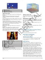
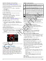
Showing the Radar Overlay

The radar overlay displays data based on the most recently 

used radar mode.

Select 

Charts

 > 

Radar Overlay

.

The radar picture appears in orange and overlays the 

navigation chart.

Setting a Custom Park Position

If you have more than one radar on your boat, you must be 

viewing the radar screen for the radar you want to adjust.
By default, the antenna is stopped perpendicular to the pedestal 

when it is not spinning. You can adjust this position.

1

From the radar screen, select 

Menu

 > 

Radar Setup

 > 

Antenna Configuration

 > 

Park Position

.

2

Use the slider bar to adjust the position of the antenna when 

stopped, and select 

Back

.

Enabling and Adjusting a Radar No Transmit 

Zone

You can indicate an area within which the radar scanner does 

not transmit signals.

NOTE: 

This feature is not available on all radar and chartplotter 

models.

1

From a radar screen, select 

Menu

 > 

Radar Menu

 > 

Radar 

Setup

 > 

Enable No Transmit Zone

.

The no-transmit zone is indicated by a shaded area on the 

radar screen.

2

Select 

Adjust No Transmit Zone

 > 

Move No Transmit 

Zone

.

3

Select 

Angle 1

, and select the new location for the first 

angle.

4

Select 

Angle 2

, and select the new location for the second 

angle.

5

Select 

Done

.

Stopping the Transmission of Radar Signals

From a Radar screen, select 

Menu

 > 

Radar Menu

 > 

Radar 

To Standby

.

TIP: 

Press   from any screen to quickly stop radar 

transmission.

Optimizing the Radar Display

You can adjust the radar display settings for reduced clutter and 

increased accuracy.

NOTE: 

You can optimize the radar display for each radar mode.

1

Select a radar range (

Adjusting the Radar Range

).

2

Restore the default value of the gain setting (

Adjusting Gain 

on the Radar Screen Automatically

).

3

Adjust the gain setting manually (

Adjusting Gain on the 

Radar Screen Manually

).

Radar Gain and Clutter

Adjusting Gain on the Radar Screen Automatically

The automatic gain setting for each radar mode is optimized for 

that mode, and may differ from the automatic gain setting used 

for another mode.

NOTE: 

Depending upon the radar in use, the gain setting 

configured for use in one radar mode may or may not be applied 

to other radar modes or to the Radar overlay.

NOTE: 

Not all options and settings are available on all radar and 

chartplotter models.

1

From a radar screen or the radar overlay, select 

Menu

 > 

Radar Menu

 > 

Gain

.

Radar

21

CONFIDENTIAL

Summary of Contents for M5APGT00

Page 1: ...Owner s Manual December 2014 Printed in Taiwan 190 01841 00_0A M5APGT00 C O N F I D E N T I A L...

Page 2: ...ort and SmartMode are trademarks of Garmin Ltd or its subsidiaries These trademarks may not be used without the express permission of Garmin The Bluetooth word mark and logos are owned by the Bluetoot...

Page 3: ...a Volvo Penta Dealer 8 Waypoints 8 Marking Your Present Location as a Waypoint 8 Creating a Waypoint at a Different Location 8 Marking an SOS Location 9 Viewing a List of all Waypoints 9 Editing a Sa...

Page 4: ...plotter in Step Steering Mode 24 Steering Patterns 24 Following the U Turn Pattern 24 Setting Up and Following the Circles Pattern 24 Setting Up and Following the Zigzag Pattern 24 Following the Willi...

Page 5: ...deo 32 Selecting a Video Source 33 Alternating Among Multiple Video Sources 33 Networked Video Devices 33 Using Video Presets on Networked Video Cameras 33 Camera Settings 33 Video Settings 33 Associa...

Page 6: ...acquire GPS signals 39 My device will not turn on or keeps turning off 39 My device is not creating waypoints in the correct location 40 NMEA 0183 Information 40 NMEA 2000 PGN Information 40 Software...

Page 7: ...nd select Next Finish Updating the Device Software Before you can update the software you must obtain a software update memory card or load the latest software onto a memory card 1 Turn on the chartpl...

Page 8: ...change the type of data shown select Overlays select a data field and select the new data type Adding a SmartMode Layout You can add SmartMode layouts to suit your needs Each customization made to one...

Page 9: ...oom out Spread two fingers apart to zoom in Selecting a Map If your product has both BlueChart g2 and LakeV HD built in maps you can select which map to use Not all models have both types of built in...

Page 10: ...or offshore deep sea fishing High Resolution Satellite Imagery Provides high resolution satellite images for a realistic view of the land and water on the Navigation chart Showing Satellite Imagery on...

Page 11: ...e vessel tracking the lost target symbol disappears from the chart or the 3D chart view Dangerous target in range The target flashes while an alarm sounds and a message banner appears After the alarm...

Page 12: ...s EPIRB and other man overboard signals Distress signal transmissions are different than standard AIS transmissions so they appear differently on the chartplotter Instead of tracking a distress signal...

Page 13: ...ne Shows and adjusts the heading line which is a line drawn on the map from the bow of the boat in the direction of travel and sets the data source for the heading line World Map Uses either a basic w...

Page 14: ...w do I make the chartplotter point me in the direction in which I want to go bearing Navigate using Go To See Setting and Following a Direct Course Using Go To How do I make the device guide me along...

Page 15: ...sing Auto Guidance a gray segment within any part of the magenta line indicates that Auto Guidance cannot calculate part of the Auto Guidance line This is due to the settings for minimum safe water de...

Page 16: ...te the route from the starting point used when the route was created to the left of the original route select Forward Port To navigate the route from the starting point used when the route was created...

Page 17: ...or more familiar destinations that require navigation through a narrow waterway Adjusting the Distance from Shore Adjusting the Distance from Shore The Shoreline Distance setting indicates how close...

Page 18: ...ntire Log 3 Review the course indicated by the colored line 4 Follow the colored line steering to avoid land shallow water and other obstacles Clearing the Active Track Select Info User Data Tracks Cl...

Page 19: ...e Starting Line Guidance You can use the starting line guidance feature to help get you cross the start line at the optimal speed during a sailing race 1 Mark the starting line Setting the Starting Li...

Page 20: ...nd sensor installed 1 Engage wind hold Engaging Wind Hold 2 Select Menu Tack Gybe 3 Select Tack or Gybe The autopilot steers your boat through a tack or gybe and information about the progress of the...

Page 21: ...equency sonar data and the other side of the screen shows a full view graph of lower frequency sonar data NOTE The split frequency sonar view requires the use of a dual frequency transducer Changing t...

Page 22: ...o reduce the intensity of the return you can reduce the color gain or contrast 1 From a sonar view select Menu Sonar Menu 2 Select an option While in the DownV or SideV sonar view select Contrast Whil...

Page 23: ...detecting fish that are close to the bottom From a sonar view select Menu Sonar Menu Sonar Setup Appearance A Scope On Selecting the Transducer Type Before you can select the transducer type you must...

Page 24: ...ata You can zoom in to the focused area which enables you to evaluate target returns more closely at a higher resolution than just zooming alone Echo Stretch Adjusts the size of the echoes on the scre...

Page 25: ...smitting Radar Signals NOTE As a safety feature the radar enters standby mode after it warms up This gives you an opportunity to verify the area around the radar is clear before beginning radar transm...

Page 26: ...get is in range A red ring flashes from the target while an alarm sounds and a message banner appears After the alarm has been acknowledged a solid red dot with a dashed red line attached to it indica...

Page 27: ...or wind the Radar overlay may not perfectly align with the chart data This situation should be avoided by using boat heading data from an electronic compass If the boat heading is based on data from...

Page 28: ...reen Automatically You can set the chartplotter to automatically adjust the appearance of clutter caused by choppy sea conditions NOTE Depending upon the radar in use the sea clutter setting configure...

Page 29: ...Source Select Settings Communications Preferred Data Source Radar 2 Select the radar source Autopilot WARNING You can use the autopilot feature only at a station installed next to a helm throttle and...

Page 30: ...screen select Menu Autopilot Menu Pattern Steering Williamson Turn 2 Select Engage Port or Engage Starboard Following an Orbit Pattern You can use the orbit pattern to steer the boat in a continuous...

Page 31: ...en prompting you to activate navigation to the man overboard location disappears Man Overboard and SOS Distress Calls Initiated from the Chartplotter When your chartplotter is connected to a Garmin NM...

Page 32: ...t Menu Gauge Setup Set Gauge Limits 2 Select a gauge 3 Select Mode Custom 4 Select an option To set the minimum value of the standard operating range select Rated Min To set the maximum value of the s...

Page 33: ...he maximum and minimum values that appear when the downwind close hauled wind gauge appears select Change Downwind Scale and set the angles To view true or apparent wind select Wind and select an opti...

Page 34: ...You can play media from sources connected to the media player and sources connected to the NMEA 2000 network Your chartplotter and iPod can be connected using a FUSION Link capable stereo Opening the...

Page 35: ...S or F Activating a SiriusXM Subscription Before you can activate the SiriusXM subscription you must have the Radio ID Locating a SiriusXM Radio ID 1 With the SiriusXM source selected tune to channel...

Page 36: ...ange in appearance if the source that provides the information changes Changing the Weather Chart 1 From a combination screen or SmartMode layout with a weather chart select Menu Weather Menu Change W...

Page 37: ...inds wave height wave period and wave direction Select Charts Sea Conditions Surface Winds Surface wind vectors appear on the Sea Conditions chart using wind barbs that indicate the direction from whi...

Page 38: ...formation 1 From a weather chart select a location on the chart 2 Select Local Weather 3 Select an option To view present weather conditions from a local weather service select Current Cond To view a...

Page 39: ...dditional options to control the camera view NOTE Not all options are available on all camera models and chartplotter models Refer to the camera manual for a list of available features You may need to...

Page 40: ...ightness arrows To adjust the screen contrast select the contrast arrows Exiting PC Display Mode 1 When in PC display mode select anywhere on the screen 2 Select the display mode icon in the upper lef...

Page 41: ...use depths of 3 feet for Auto Guidance route calculations Safe Height Sets the minimum height chart height datum of a bridge that your boat can safely travel under Shoreline Distance Sets how close to...

Page 42: ...plotter to a Garmin Marine Network to receive data from and share data with other Garmin Marine Network compatible devices and chartplotters Setting Alarms Navigation Alarms Select Settings Alarms Nav...

Page 43: ...ort Setting the Vessel Type You can select your boat type to configure the chartplotter settings and to use features customized for your boat type 1 Select Settings My Vessel Vessel Type 2 Select Powe...

Page 44: ...he chartplotter Copy the data from HomePort to the prepared memory card For more information see the HomePort help file Selecting a File Type for Third Party Waypoints and Routes You can import and ex...

Page 45: ...e On 3 Go to a screen you want to capture 4 Hold Home for at least six seconds Copying Screenshots to a Computer 1 Remove the memory card from the chartplotter and insert it into a card reader that is...

Page 46: ...Water temperature SDVHW VHW Water speed and heading Receive DPT Depth DBT Depth below transducer MTW Water temperature VHW Water speed and heading WPL Waypoint location DSC Digital selective calling...

Page 47: ...e trade secrets of Garmin and or its third party providers and that the Software in source code form remains a valuable trade secret of Garmin and or its third party providers You agree not to decompi...

Page 48: ...gine gauges 26 configuring 26 status alarms 26 EPIRB 6 event log 34 F factory settings 37 stations 2 favorites 2 Fish Eye 3D sonar cone 7 suspended targets 7 tracks 7 fishing chart 3 32 setup 7 fuel a...

Page 49: ...nce 17 noise 16 recording 18 19 scroll speed 17 sharing 15 16 SideV 15 source 15 16 surface noise 17 suspended targets 18 views 14 15 waypoint 15 whiteline 18 zoom 16 SOS 9 25 stations 1 changing the...

Page 50: ...699 52 001 855 792 7671 0800 0233937 47 815 69 555 00800 4412 454 44 2380 662 915 35 1214 447 460 386 4 27 92 500 0861 GARMIN 427 646 27 0 11 251 9999 34 93 275 44 97 46 7744 52020 886 2 2642 9199 ext...

Reviews: