
2
Use cable ties to secure the transducer cable to the shaft or
other secure location.
3
Route the Ethernet cable to the network switch or to the back
of the chartplotter.
4
Route the power cable through a switched or unswitched 10
to 35 Vdc power source.
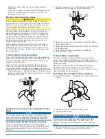
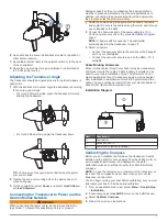
Adjusting the Transducer Angle
The transducer should be angled properly for optimal imagery in
each mode.
1
With the transducer mounted, angle the transducer according
to the mode you will use:
• For LiveVü Forward mode, angle the transducer forward
and slightly downward.
• For LiveVü Down mode, angle the transducer down.
TIP:
You may want to experiment to find the best angle for
your sonar needs.
2
Tighten the knob or mounting bolt so the device does not
move during use.
3
On the chartplotter, select
Sonar
, and select
LiveVü Down
or
LiveVü Forward
.
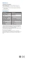
Connecting the Transducer to Power and the
Garmin Marine Network
WARNING
When connecting the power cable, do not remove the in-line
fuse holder. To prevent the possibility of injury or product
damage caused by fire or overheating, the appropriate fuse
must be in place as indicated in the product specifications. In
addition, connecting the power cable without the appropriate
fuse in place voids the product warranty.
1
Route the cables using the appropriate tie wraps, fasteners,
and sealant to secure the cables along the route, and through
any bulkheads or the deck.
2
Connect the bare-wire end of the power cable to a 10 to
35 Vdc power source and to the ground
NOTE:
A power switch is optional. The chartplotter
automatically turns the transducer on and off.
3
Select an option:
• Connect the network cable to the network or the Panoptix
port on your chartplotter.
• Connect the network cable to a port on the GMS
™
10, if
available.
Cable Routing Grommets
When routing cables through your boat, it may be necessary to
drill holes to route the cables. Cable routing grommets can be
used to cover cable installation holes. The grommets do not
create a waterproof seal. If necessary, apply a marine sealant
after installation to weatherproof around the grommet and the
cable. You can purchase grommets from your Garmin dealer or
directly from Garmin at
.
Installation Diagram
+
-
Item
Description
À
Chartplotter
Á
Panoptix PS22-TR
Â
Power source (switch is optional)
Calibrating the Compass
Before you can calibrate the compass, the transducer must be
installed on the shaft far enough away from the trolling motor to
avoid magnetic interference, and deployed in the water.
Calibration must be of sufficient quality to enable the internal
compass.
NOTE:
To use the compass, you must mount the transducer on
the shaft. The compass does not work when you mount the
transducer on the motor.
You can begin turning your boat before calibrating, but you must
fully rotate your boat 1.5 times during calibration.
1
From an applicable sonar view, select
Menu
>
Sonar Setup
>
Installation
.
2
If necessary, select
Use AHRS
to turn on the AHRS sensor.
3
Select
Calibrate Compass
.
4
Follow the on-screen instructions.
3


