Page 9
SeeLeveL Sender Installation Manual 710-JS / 710-ES / 710-SS
WIRING THE SENDER
❸
Connect the wiring to the pigtail
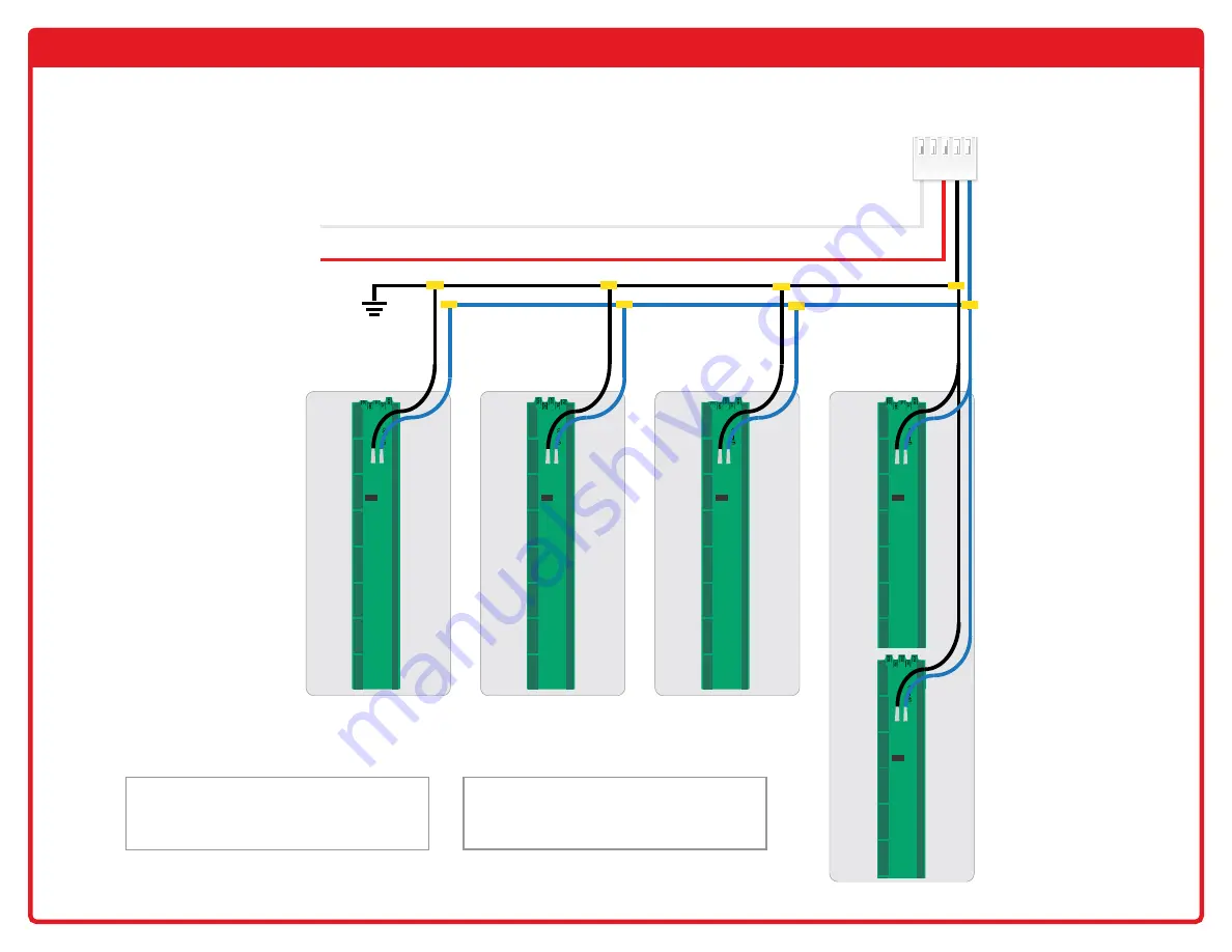
The following diagram shows the wiring from the sender to the display pigtail. Other wiring
connections may apply for each display model. All wiring diagrams are available on the website.
GROUND
TO
+12V POWER
TO PUMP
INDICATOR
PIGTAIL
HARNESS
GALLEY
BLACK
GREY
FRESH STACKED
W
CAUTION:
It is very important that the display
and senders have the same ground. Make sure the
sender ground connection is connected back to the
display ground or breaker panel ground.
W
CAUTION:
Wires are to be routed to the RIGHT
side of the sender, away from the sender. Never
route the wires to the left of the sender. If they
drape over the sender they could affect the reading.
Example of stacked
sender wiring


