USER’S MANUAL
-
20
-
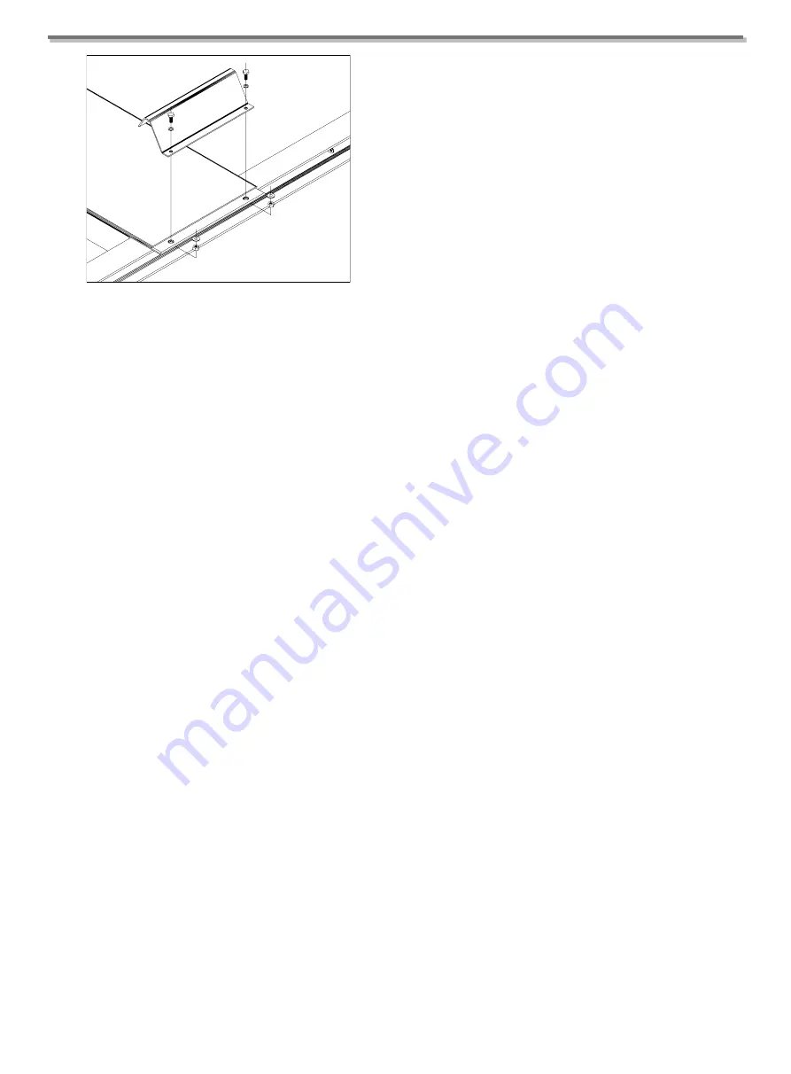
Fig. 52
Fit the ramps by slotting them into the platforms on the
required end and then fix the wheel stops on the opposite.
4.8 ADJUSTING THE LIFTING CABLES
Drive a vehicle onto the lift.
Raise the lift to the maximum height and check if the four
wedges are fitted inside the slots of the safety rods.
Check if the distance between the wedges and the slots of
the safety rods on the 4 posts is at least 20 mm from the
support; a lower value would not allow the safety device to
rotate, and it would stay attached to the rod.
If necessary, level the unit by adjusting the nuts on the
terminals of the cables and the limit micro switch.
When the adjustment is completed, lock with the lock nuts.
IMPORTANT: This adjustment must be repeated 1 or 2
weeks after setting up the lift.
4.9
PRELIMINARY
TESTS
AND
INSPECTIONS BEFORE STARTING
MECHANICAL CHECKS
●
Leveling and alignment;
●
Tightness of bolts, unions and connections;
●
Free movement of all moving parts;
●
Cleaning of the different machine parts;
●
Position of guards and protections.
ELECTRICAL CHECKS
●
Correct connections in accordance with wiring
diagrams;
●
Earth connection of the lift;
●
The operation of:
- Lifting limit switch;
- Lowering micro-switch;
- Solenoid valve in the hydraulic system.
HYDRAULIC CHECKS
●
Make sure the reservoir is filled with sufficient oil;
●
Check for leaks;
●
Make sure the cylinder is working properly.
N.B. If there is insufficient oil, top up the reservoir to the
correct level.
See
Chapter 6 “MAINTENANCE”
for details of the
procedure.
CHECKING MOTOR ROTATION DIRECTION
Check that the motor is turning as indicated by the arrow
on the control unit hydraulic pump; do this by running the
machine momentarily (maximum 2 seconds to avoid
damage).
If the hydraulic system is not working properly, consult the
fault diagnosis chart in
Chapter 7
.
WARNING
THE FOLLOWING OPERATIONS ARE TO BE
PERFORMED EXCLUSIVELY BY TECHNICIANS
FROM THE AUTHORISED SERVICE CENTRE
specified on the title page.
No-load check (no vehicle on lift)
Check, in particular:
●
that the LIFT and LOWERING buttons are working
properly;
●
that the lift reaches its maximum elevation;
●
that there are no undue vibrations in the posts or the
cross-pieces;
Summary of Contents for TFA4500-3D
Page 2: ......
Page 4: ...USER S MANUAL ii...
Page 7: ...USER S MANUAL 3 Chapter 2 SPECIFICATIONS 2 1 OVERALL DIMENSION TFA4500 3D...
Page 8: ...USER S MANUAL 4 TFA5000 3D...
Page 9: ...USER S MANUAL 5 TFA5500 3D...
Page 10: ...USER S MANUAL 6 TFL5000 3D...
Page 31: ...USER S MANUAL 27 APPENDIX B HYDRAULIC DIAGRAM...
Page 32: ...USER S MANUAL 28 APPENDIX C ELECTRICAL WIRING DIAGRAM C 1 380V ELECTRICAL WIRING DIAGRAM...
Page 33: ...USER S MANUAL 29 C 2 220V ELECTRICAL WIRING DIAGRAM...
Page 35: ...USER S MANUAL 31 EXPLOSIVE DIAGRAM...
Page 36: ...USER S MANUAL 32...
Page 37: ...USER S MANUAL 33...


