USER’S MANUAL
-
2
-
●
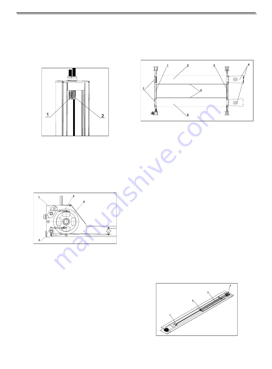
The end of the steel cable
(Fig. 3-1)
, which is fitted
with an M20 threaded shank (fixed with M20 nut and
lock nut, class 6S).
The length of the cables can be perfectly adjusted, also to
take up slack due to stretching, thanks to the length of the
threaded shanks on the ends of the cables.
Fig. 3
1.2 MOVABLE STRUCTURE
The movable structure consist of two cross-pieces and two
platforms.
Each cross-piece translates vertically between two posts.
Fig. 6
As shown in
Fig.6
, the ends of the cross-pieces are fitted
with the following parts:
●
Return pulleys
(Fig. 6-4)
for the lift cable
●
Mechanical safety devices (wedges)
(Fig. 6-1 and
Fig. 6-2)
The wedge
(Fig. 6-2)
will engage automatically during
lifting and when the lift is raised. To start the LOWERING
cycle the wedges must be disengaged by hand or using an
electro-pneumatic control (optional) when lowering.
The safety wedge
(Fig. 6-1)
take the weight in the event
of a cable failure; the wedge automatically engages with
the safety rods and immediately stops the movable section
of the lift together with the vehicle; the cable micro-switch
disconnects the electrical parts.
The two platforms
(Fig. 7)
are supported on the cross-
pieces.
Fig. 7
The right platform
(Fig. 7-6)
has no adjustment; the left
platform
(Fig. 7-2)
is free to slide across the width of the
lifting area to adapt to the track width of the vehicle being
lifted.
Both platforms have inside rails
(Fig. 7-6)
for rolling jack,
and fixed wheel stops
(Fig. 7-7)
to stop the vehicle from
going beyond the ends of the platforms.
The access ramps
(Fig. 7-4)
, pivoted to the platforms,
automatically reach a vertical position when the platforms
lift, thereby securing the vehicle also from the access end.
The following components are located beneath the fixed
platform
(Fig. 8)
, and are accessible only from underneath:
●
Hydraulic lift cylinder
(Fig. 8-3)
●
Parachute safety valve
(Fig. 8-2)
●
Clevis coupling
(Fig. 8-1)
for the steel cables
●
Two cable return pulley assemblies
(Fig. 8-4)
Fig. 8
Summary of Contents for TFA4500-3D
Page 2: ......
Page 4: ...USER S MANUAL ii...
Page 7: ...USER S MANUAL 3 Chapter 2 SPECIFICATIONS 2 1 OVERALL DIMENSION TFA4500 3D...
Page 8: ...USER S MANUAL 4 TFA5000 3D...
Page 9: ...USER S MANUAL 5 TFA5500 3D...
Page 10: ...USER S MANUAL 6 TFL5000 3D...
Page 31: ...USER S MANUAL 27 APPENDIX B HYDRAULIC DIAGRAM...
Page 32: ...USER S MANUAL 28 APPENDIX C ELECTRICAL WIRING DIAGRAM C 1 380V ELECTRICAL WIRING DIAGRAM...
Page 33: ...USER S MANUAL 29 C 2 220V ELECTRICAL WIRING DIAGRAM...
Page 35: ...USER S MANUAL 31 EXPLOSIVE DIAGRAM...
Page 36: ...USER S MANUAL 32...
Page 37: ...USER S MANUAL 33...


