


Garrecht Avionik GmbH
TRX-2000 ADS-B Traffic Monitor
User Manual
Revision: 1.0b
18
19 DEC 2011
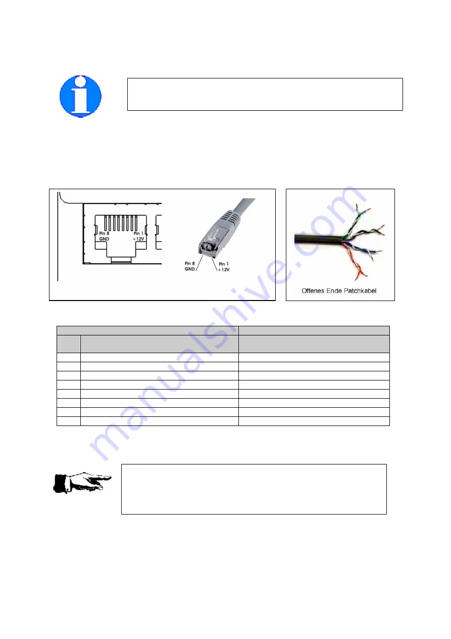
2.4.2.2. Pinout of the RJ-45 connectors
Remember, that the TX/RX lines of port 2 and port 3 (CDTI interfaces) are reversed to the IGC
standard. Pin 3 provides a 3.3V DC power supply for powering external FLARM displays. This makes
the interface compatible to existing external FLARM compatible displays.
Power can be supplied via each port. Be sure to power only FLARM and TRX-2000 via these lines to
prevent exceeding the maximum current.
Pinout Port 1
Pin
#
Function
Wire color of supplied connection
cable (acc. to EIA/TIA 568B)
1
+ 9 - +28 V DC
Brown
2
+ 9 - +28 V DC
Brown-White
3
n.c. (not connected)
Green
4
n.c. (not connected)
Blue-White
5
RX 1 (Data input 1)
Blue
6
TX 1 (Data output 1)
Green-White
7
GND
Orange
8
GND
Orange-white
It is recommended to power the TRX-2000 via port 1. Use the NMEA data provided on port 1 to feed
your Mode-S transponder for ADS-B out purposes. The baudrate can be set up using the TRX-Tool.
Pinbelegung RJ-45 Buchse
To prevent injury on the TRX-2000 and/or connected devices, always
check the pinout of the used connection cable.
Damages caused by reverse polarity or wrong connection are not covered
by the manufacturer's warranty.
The pinout complies with the standards of the International Gliding
Commission (IGC) for flight recoders. The pin numbering is reversed to the
industrial standard.


