background image

Magnum 4K8 Switches      Installation and User Guide      (10/04) 


17 

www  GarrettCom  com

.

.


MAGNUM 4K-Series

Ethernet 10/100 Switch

1           2           3           4             5           6           7            8

POWER

ERROR

L/

SPEE

F/H

UPLINK

=      X

A  L

F

H

F

H

MAGNUM 4K-Series

Ethernet 10/100 Switch

1           2           3           4             5           6           7            8

POWER

ERROR

L/

SPEE

F/H

UPLINK

=      X

A  L

F

H

F

H

MAGNUM 4K-Series

Ethernet 10/100 Switch

1           2           3           4             5           6           7            8

POWER

ERROR

L/

SPEE

F/H

UPLINK

=      X

A  L

F

H

F

H

MAGNUM 4K-Series

Ethernet 10/100 Switch

1           2           3           4             5           6           7            8

POWER

ERROR

L/

SPEE

F/H

UPLINK

=      X

A  L

F

H

F

H

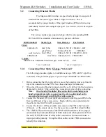
2.   Connect the other end of the cable to the corresponding device 

3.   Use the LINK LED to ensure proper connectivity by noting that the LED will be 

illuminated when the unit is powered and proper connection is established. 

3.3      Rack-mounting 


Installation of a 

Magnum 4K8 Switch in a 19” 

rack is a simple procedure. The 

units are 1U (1.70”) high. When 

properly installed, the front-mounted LED status indicators should be in plain view and 

easy to read. Rack-mount installation requires special 19” rack-mounted brackets and 

screws (included with each 4K8 unit). The brackets attach to the front sides of the 

Switch, which is then fastened into a standard 19” RETMA rack. 


The 23” brackets and ETSI brackets are also available (optional) for rack-

mounting of Magnum 4K Series Switches. The 23” brackets are popular in the Telco 

industry where they are a standard for Central Office rack mounting purposes. The 23” 

brackets are mainly being used for larger equipment assemblies in rack-mounting frames, 

and are frequently accessed in 

operation from both sides. 


The ETSI (European 

Telephone Standard) brackets 

are similar to the 19” brackets 

but use metric dimensions. 

The optional 23” 

brackets and the ETSI brackets 

come as a pair in a package, 

along with the necessary screws 

for attaching the brackets to the 

sides of the Magnum Switch 

unit.  


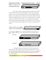
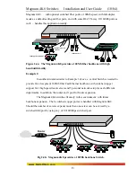
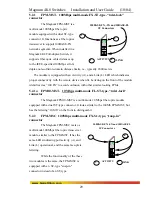
Fig 3.3 Multiple Magnum 4K8 units rack-mounted in a 23” frame 


MAGNUM 4K-Series

Ethernet 10/100 Switch


1           2           3           4             5           6           7            8

POWE R

ERROR

L/A

S PE ED

F/H

U PLINK

=      X

A     L

F

H

F

H

Summary of Contents for 4K-Series

Page 1: ...www GarrettCom com Magnum 4K Series 4K8 Switches Installation and User Guide 5 00 USD...

Page 2: ...itch are trademarks and Personal Hub is a registered trademark of GarrettCom Inc Important Magnum 4K Series Fiber Switches contain no user serviceable parts Attempted service by unauthorized personnel...

Page 3: ...s may cause harmful interference in a residential installation This equipment generates uses and can radiate frequency energy and if not installed and used in accordance with the instructions may caus...

Page 4: ...Fiber Optic 16 3 2 4 Connecting Twisted Pair RJ 45 CAT3 CAT5 16 3 3 Rack mounting 17 3 4 Fiber Port Module FPM Installation 18 3 4 1 Preparation for Installing and Removing FPMs 18 3 4 2 Installing FP...

Page 5: ...ackaging Information 34 APPENDIX A WARRANTY INFORMATION 34 APPENDIX B INTERNAL DC POWER SUPPLY OPTIONS 35 APPENDIX C INTERNAL DC DUAL SOURCE POWER OPTION 37 Revisions 10 04 minor updates 04 03 Edited...

Page 6: ...tching performance Outdoor Ethernet Switch for temperature uncontrolled locations 6 10 100 and 2 100Mb fiber ports can be connected in strings Mixed Media Fiber Hub 16 port Stackable 10 100 auto sensi...

Page 7: ...ed pair 150 m 492 ft 100BASE FX half duplex multi mode 412 m 1350 ft 100BASE FX full duplex multi mode 2 0 km 6 562 ft 100BASE SX short wavelength HDX m m 300 m 935 ft 100BASE FX half duplex single mo...

Page 8: ...Power Supply Internal AC Power Connector IEC type male recessed at rear of chassis with adjacent manual ON OFF switch on AC models only Input Voltage 110 to 240 VAC auto ranging Input Frequency 47 to...

Page 9: ...ber Port Modules for Magnum 4K Series 4K8 Switches only FPM MSC Fiber module for 4K8 Switches with 100Mbps multi mode FX SC connectors FPM MST Fiber module for 4K8 Switches with 100Mbps multi mode FX...

Page 10: ...er Cord U S and other 115 VAC only 1 Set of metal Ears for rack mounting 1 Installation and User Guide this manual 1 Product Registration Card Remove the items from the shipping container Be sure to k...

Page 11: ...in network traffic centers or multi system power users the Magnum 4K8 Switches are easy to install and use Addresses of attached nodes are automatically learned and maintained adapting the switching s...

Page 12: ...r and a manual ON OFF power switch located at the rear Fan driven cooling air flows left to right Figure 2 2 1b Rear view Magnum table top rack mount 4K8 Switch 2 2 2 Magnum 4K8R Reverse model front L...

Page 13: ...modules 100Mb fiber Fig 2 2 3 Fiber Port Modules FPM ST FPM SC FPM MTRJ The fiber port module is optional for Magnum 4K8 Switch In a fiber port module all of the fiber ports are of the fixed speed at...

Page 14: ...setting for operation at 10 or 100Mb speed in full or half duplex mode They independently move to half duplex mode at 10 Mb or at 100Mb speed if the device at the other end of the twisted pair cable i...

Page 15: ...ffic load is greatest To minimize the possibility of dropping frames on congested ports each Magnum 4K8 Switches dynamically allocates buffer space from an 1MB memory pool ensuring that heavily used p...

Page 16: ...nal on all receiving half duplex ports in order to stop incoming traffic The latency the time the frame spends in the Switch before it is sent along or forwarded to its destination of the 4K8 Switches...

Page 17: ...lf duplex operation auto sensing All fiber and RJ 45 copper ports are capable of half or full duplex individually selected All RJ 45 ports support 10 100 auto negotiation Rack mounting may be std or r...

Page 18: ...er backbone segments in the network center the Switch needs to provide high speed switched support for two central servers for a 100MB connection to a router and for a dual speed hub serving a local w...

Page 19: ...Magnum 4K8 switches fit nicely in this environment with future backbone expansion The 8 switched copper ports are handled with Magnum 4K8 Should the number of servers expand more than one server can...

Page 20: ...d or multiple rack assembly verify that the equipment has a reliable and uncompromised earthing path 6 If the intra building wiring cabling is involved with this product NEBS then it is recommended to...

Page 21: ...ocedure applies to ports using a FPM MST or FPM10 MST 1 Before connecting the fiber optic cable remove the protective dust caps from the tips of the connectors on the FPM Save these dust caps for futu...

Page 22: ...ow the steps listed in Section 3 2 2 above 3 2 4 Connecting Twisted Pair RJ 45 CAT3 CAT5 Unshielded or Shielded The RJ 45 ports of the Magnum 4K Series can be connected to the following two media type...

Page 23: ...rs should be in plain view and easy to read Rack mount installation requires special 19 rack mounted brackets and screws included with each 4K8 unit The brackets attach to the front sides of the Switc...

Page 24: ...le code de puissance est d branch du ch ssis avant d essayer au retirer et ou substitue toutes les cartes de FPM Le manque de faire ainsi le r sultat dans les dommages l unit et videra la garantie Cau...

Page 25: ...Caution Be careful not to disturb the power supply Attention Faites attention ne pas d ranger l alimentation d nergie Looking down into the Magnum 4K8 unit notice that there are one FPM connector soc...

Page 26: ...ds in the Magnum 4K8 Switches Up to sixteen front mounted FPM card may be installed in one Magnum 4K8 Switch unit Follow these steps to install a FPM Step 1 Remove front top chassis cover See procedur...

Page 27: ...e plate Magnum FPM BLNK to cover the slot opening in the front panel This will maintain proper cooling air flow safety and operation as required by FCC CE and other regulations Step 4 Once FPM cards h...

Page 28: ...discussed in Section 3 4 1 3 5 Powering the Magnum 4K8 Switch The Magnum 4K Series Switches incorporate an internal universal power supply and has a Figure 3 5 Magnum 4K8 AC power connector recessed...

Page 29: ...below Filtering and Forwarding Each time a packet arrives on one of the switched ports the decision is taken to either filter or to forward the packet Packets whose source and destination addresses ar...

Page 30: ...in or to be cascaded push out to a 10 100Mb repeater or switching hub in the network Verify proper Up link push button position by noting Port 1 s LK link LED status which is illuminated when a proper...

Page 31: ...n is potentially an externally controlled process the original highest order mode result can change at any time depending on network changes that may occur If the device at the other end is not an aut...

Page 32: ...ference makes the 10Mb port unable to keep up It can also occur when multiple 100Mb ports are attempting to transmit to one 100Mb port and in other protracted heavy traffic situations Magnum 4K Series...

Page 33: ...ve length nm Cable Size m X mitr Output PT dB R cvr Sens PR dB Worst OPB dB Worst distance Km fdx typical OPB dB typical distance Km fdx FPM10 FST 10 Mb FL Multi mode 2 2 850 62 5 125 100 140 50 125 1...

Page 34: ...ith illustrations Remove the FPM s from the shipping container Be sure to keep the shipping container should you need to ship any of the FPMs separately at a later date In the event there are items mi...

Page 35: ...identifies it as 100 FX to avoid confusion with other similar looking FPMs 5 2 1a FPM10 MST 10 Mbps multi mode FL ST type twist lock connector The Magnum FPM10 MST is a multi mode 10 Mbps fiber optic...

Page 36: ...LINK L LEDs identical to those of the FPM MSC To distinguish the single mode FPM SSC from the multi mode FPM MSC the label Sgl M is at the top of the faceplate of the FPM SSC 5 2 4 FPM MTRJ 100Mb mul...

Page 37: ...not in use its appearance is distinctive because it has a tiny hinged door over the port hole to act as a dust cover When installed in a Magnum 4K8 Full duplex Switch it supports fiber optic cable dis...

Page 38: ...he Installation Section of the applicable chapter of this manual Also check to make sure that the various components of the network are interoperable 2 Check the cables and connectors to ensure that t...

Page 39: ...ations terminals and printers plus the various network media types being used 4 A record of changes that have been made to your network configuration prior to the occurrence of the problem Any changes...

Page 40: ...yrofoam popcorn type packing material This material may cause electro static shock damage to the unit 2 Clearly mark the Return Material Authorization RMA number on the outside of the shipping contain...

Page 41: ...24VDC 125VDC power option are designed using diodes inside on each DC power input line behind the two external power connection terminals so that the power from an external source can only flow into t...

Page 42: ...s section describes the installation of the 48 VDC 24VDC 125VDC power source leads to the 48 VDC 24VDC 125VDC power terminal block on the Magnum Ks see figure at the right In this picture the 48VDC te...

Page 43: ...0 for troubleshooting APPENDIX C INTERNAL DC DUAL SOURCE POWER OPTION C1 0 SPECIFICATIONS FOR MAGNUM 4K SERIES FIBER SWITCH Power Supply Internal 48VDC Dual Source model Dual Src 48V DC Power Connect...

Page 44: ...er DC power is correctly applied to either or both of the two inputs C4 0 FEATURES AND BENEFITS OF THE DUAL SOURCE DESIGN a The Switch unit can receive power from either input A or B The hub will norm...

Page 45: ...tional it connects to the chassis Ensure that each lead is securely tightened The 24VDC 125VDC terminal block on Magnum 4K Series Switch also has everything similar to 48VDC info Described above C5 1...

Reviews: