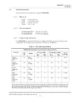
C
HAPTER
1 -
Introduction
Controls and Indicators
DS2000-IFR Installation and Maintenance Guide
1 - 6
1.3.2
DS2000-IFR
Indicators
The
DS2000-IFR
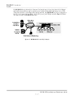
has LED indicators on the front panel which provide immediate information concerning
the status for the standard port connections. Status indicators are also located under the Ethernet ports on the
rear of the unit. Refer to
Figure 1-3
for locations of the LEDs. The LEDs are described in
Table 1-4
, below.
Figure 1-3.
DS2000-IFR
LEDs
Table 1-4. LEDs
LED Name/Location
Condition
Indication
Front Panel LEDs
Ethernet/
LED for port E0
On
Indicates connectivity to another active Ethernet
device for port E0 only
Off
Indicates no connection to an active Ethernet
device or network for port E0 only
Flashing
Data is passing through the E0 port
Auxiliary 1/
AUX1
On (Amber)
N/A (not used)
Auxiliary 2/
AUX2
On
Green - indicates that there is a "Link" to an
Ethernet device on one of the Ethernet ports (E1-
E10)
Amber - indicates no active Ethernet devices
connected to ports E1 - E10.
EthernetAuxil
iary
1
Au
xiliar
y 2
Syn
c/As
ync
Asy
nc
HS
WA
N 1
HS
WA
N 2
System
Made in USA
Front Panel LEDs
Ethernet Port LEDs
Rear Panel
Ethernet
RS232(DEBUG) E0 AUX1 S0 CON AUX 2
W1
W2
Ethernet Board LED
Summary of Contents for DynaStar DS2000-IFR
Page 2: ......

