background image

C

HAPTER

3 -

Installation

Connecting Facility Power

DS2000-IFR Installation and Maintenance Guide

3 - 5

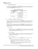
3.4.2 AC Power Connection

For AC powered units the connections are to the Power input terminals on the rear of the

DS2000-IFR

as

shown in

Figure 3-1

. Connect AC power to the unit as follows.

1.

Ensure that the facility AC power is shut off to the wires being connected to the

DS2000-IFR

.

2.

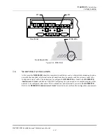
Lift the protective cover from the Power input and loosen the screws and the Ground lug bolt
beside the nonpolarized power inputs of the

DS2000-IFR

, as shown in

Figure 3-1

.

3.

Connect the facility ground connection and tighten to 32 inch lbs.

4.

Connect the two facility AC wires to the nonpolarized power input points and tighten the screws to
ten inch lbs. Push the protective cover over the screw heads and route the wires through the
cutouts.
The facility AC wires should be 14 AWG and be terminated with a #6 ring lug.

5.

At the facility AC power source apply power to the

DS2000-IFR

.

6.

The System and Ethernet board LEDs, shown in

Figure 1-3 on page 1-6

, will illuminate green

after roughly 20 seconds.

ELECTRICAL WARNING: Verify that a proper ground connection is made from the ground
lug to facility ground prior to connecting power to the

DS2000-IFR

. Failure to have a

proper ground path could cause serious injury or death to personnel in cases of power
surges.

Summary of Contents for DynaStar DS2000-IFR

Page 1: ...mber 3 01 0088 01 Rev AA GarrettCom Inc 25 Commerce Way 1 North Andover MA 01845 Phone 978 688 8807 Fax 978 688 8771 DynaStar 2000 Industrial Frame Router DS2000 IFR Installation and Maintenance Guide 5 00 USD ...

Page 2: ......

Page 3: ...ights Except as set forth in the Software License Agreement Dymec Inc makes no representation that software programs and practices described herein will not infringe on existing or future patent rights copyrights trademarks trade secrets or other proprietary rights of third parties and Dymec Inc makes no warranties of any kind either express or implied and expressly disclaims any such warranties i...

Page 4: ...IES ARE EXCLUSIVE AND IN LIEU OF ALL OTHER EXPRESS AND IMPLIED WARRANTIES EXCEPT WARRANTIES OF TITLE INCLUDING BUT NOT LIMITED TO IMPLIED WARRANTIES OF MERCHANTABILITY AND FITNESS FOR A PARTICULAR PURPOSE LIMITATION OF LIABILITY Anything to the contrary herein contained notwithstanding DYMEC INC ITS CONTRACTORS AND SUPPLIERS OF ANY TIER SHALL NOT BE LIABLE IN CONTRACT IN TORT INCLUDING NEGLIGENCE ...

Page 5: ... EQUIPMENT No equipment may be returned without purchaser first obtaining DYMEC Inc s written Return Material Authorization RMA Equipment accepted for credit not involving a DYMEC Inc error shall be subject to all the terms of the original purchase contract and to a service charge of 20 of the invoice price Returned equipment must be of current manufacture unused and in reasonable condition secure...

Page 6: ...tled Digital Apparatus ICES 003 of the department of Communications Cet appareil numérique respecte les limites bruits radioélectriques applicables aux appareils numériques de Class A prescrites dans la norme sur le materiel brouilleur Appareils Numériques NMB 003 édictée par le ministre des Communications EN55022 Warning This is a Class A product In a domestic environment this product may cause r...

Page 7: ...d by the supplier Any repairs or alterations made by the user to this equipment or equipment malfunctions may give the telecommunications company cause to request the user to disconnect the equipment Avis Avant d installer ce matériel l utilisateur doit s assurer qu il est permis de le raccorder aux installations de l entreprise locale de télécommunication Le matériel doit également être installé ...

Page 8: ...T ou SJT à trois conducteurs d une longueur maximale de 15 pieds muni d une prise à lames parallèles avec mise à la terre et pouvant supporter 15 A à 125 V Dans le cas des unités devant fonctionner sous 250 V c a conformément aux normes internationales utilisez un cordon d alimentation homologue UL constitué au minimum d un cordon de calibre 14 AWG 0 83 mm3 muni d une prise avec mise à la terre po...

Page 9: ...v EN55022 iv Safety iv Class 1 Laser Products v Laser Radiation and Connectors v Service Personnel Warning vi Conformité UL E U et Canada vi Grounding vi PREFACE About This Manual ix Conventions ix Related Documents x Web Access x Comments x CHAPTER 1 INTRODUCTION 1 1 Overview 1 1 1 2 Specifications 1 3 1 2 1 Physical 1 3 1 2 2 Environmental 1 3 1 2 3 Optical Specifications 1 3 1 2 4 Compliance 1 ...

Page 10: ...er Organization 3 1 3 2 Unpacking The DS2000 IFR 3 1 3 2 1 Install Optional Ethernet Fiber Optic SFP Ports 3 2 3 3 Installation 3 3 3 3 1 Rack Mounting 3 3 3 4 Connecting Facility Power 3 4 3 4 1 DC Power Connection and Applying Power 3 4 3 4 2 AC Power Connection 3 5 3 5 Connecting Network Cables 3 6 3 5 1 Connecting Serial Cables 3 6 3 5 2 Connecting Ethernet Cables 3 7 3 5 3 Connecting Fiber Et...

Page 11: ...onvention used throughout the manual which is the use of callouts interspersed in the text of the document These callouts shown and described below draw the user s attention to a condition or situation that may require them to act or at least to be informed of All callouts will appear immediately before the step which the callout information pertains The callouts are listed below with descriptions...

Page 12: ...al steps needed to get the unit into operation Also included are explanations of the additional options available to the user for managing and monitoring the network WEB ACCESS All of the DS2000 IFR manuals are available in pdf format on the Dymec website www dymec com COMMENTS If you find an error or have a helpful tip on the layout or informational content of this or any other Dymec manual pleas...

Page 13: ...on site use and acts as a WAN access device The DS2000 IFR comes in various configurations with dual WAN connections DDS or T1 E1 eight or ten Ethernet ports with optional SFPs and 16 Serial ports The DS2000 IFR can also be ordered with either a High or Low voltage power supply The standard configurations of the DS2000 IFR are shown in Figure 1 1 Figure 1 1 DS2000 IFR Configurations RS232 DEBUG E0...

Page 14: ...s over a WAN Wide Area Network to controlling and monitoring functions The DS2000 IFR can also be configured to provide on site connectivity for Ethernet and Serial devices to local Ethernet networks Figure 1 2 shows the connectivity that the DS2000 IFR provides Figure 1 2 DS2000 IFR Connectivity Example Serial Ethernet Substation Network Alfred Data Network Monitoring SCADA Computer Center Substa...

Page 15: ...l maximum distance is an estimated projection based on typical fiber installations actual distance will depend on actual network attenuation For all MM multimode optics the recommended fiber cable type is 62 5 125 µm fiber Selected others are supported including 50 125 µm fiber for 100FX and 85 125 µm and 100 140 µm for 100 FX only For 100FX SM single mode optics the recommended fiber cable type i...

Page 16: ...the table below see Table 1 2 Safety UL60950 EN60950 CE Mark CSA Industrial IEEE 1613 Emissions EN55022A FCC Part 15A VCCI AS NZ 3548 Immunity EN55024 2003 EN61000 6 2 EN61000 4 2 ESD EN610000 4 3 RF EN61000 4 4 EFT EN61000 4 5 Surge EN61000 4 6 CRF EN610000 4 11 VDI Telecom ACTA TIA ESI IS 968A Formerly FCC Part 15 EN55022 1998 Telco Port Emissions Table 1 2 Power Requirements Power Supply Option...

Page 17: ... capable devices or network Ports S1 S16 RJ45 Connection to serial async devices Configurable to 300 600 1200 2400 4800 9600 and 19 2 28 8 33 6 38 4 57 6 115 2 230 4 Kbps W1 and W2 RJ48 56 64 Kbps DDS CSU DSU WAN connection Refer to labeling on the DS2000 IFR for WAN port type W1 and W2 RJ48 T1 E1 CSU DSU WAN connection Refer to labeling on the DS2000 IFR for WAN port type RS232 DEBUG DB15 female ...

Page 18: ...n Condition Indication Front Panel LEDs Ethernet LED for port E0 On Indicates connectivity to another active Ethernet device for port E0 only Off Indicates no connection to an active Ethernet device or network for port E0 only Flashing Data is passing through the E0 port Auxiliary 1 AUX1 On Amber N A not used Auxiliary 2 AUX2 On Green indicates that there is a Link to an Ethernet device on one of ...

Page 19: ...wn or not configured properly HS WAN 2 LED for W2 port either T1 E1 or DDS On Indicates an active circuit Off Indicates Frame circuit is down or not configured properly Flashing Data is passing through the port System Off No power applied to unit Red Reset state system is not loaded Amber System is being booted Green Normal operation Rear Panel LEDs Ethernet E1 through E10 when populated On Indica...

Page 20: ...l emulation to access the device a null modem cable is required Location Port Name Connection Type Port Type Pinout Table Reference Ports E1 through E8 as populated and E0 RJ45 Ethernet Table 1 5 Ports E7 and E8 optional SFP for 10 100 Mbps fiber optic ports LC Ethernet Table 1 6 Ports E9 and E10 optional SFP for Gbps fiber optic ports LC Ethernet Table 1 6 S1 through S16 RJ45 Serial Table 1 7 W1 ...

Page 21: ... RJ45 Pin Signal 1 Request To Send RTS 2 Data Set Ready DSR 3 Transmit Data TxD 4 Receive Data RxD 5 Ground GND 6 Data Terminal Ready DTR 7 Data Carrier Detect DCD 8 Clear To Send CTS Table 1 8 W1 and W2 DDS Ports RJ48 Pin Signal 1 Transmit Data Ring 2 Transmit Data Tip 3 Not Used 4 Not Used 5 Not Used 6 Not Used 7 Receive Data Tip 8 Receive Data Ring Rx Tx Pin 8 Pin 1 Pin 8 Pin 1 ...

Page 22: ...0 S0 Sync Async RJ69 ten pin RJ45 Pin Signal 1 Tx Clock 2 Data Carrier Detect DCD 3 Receive Data RxD 4 Transmit Data TxD 5 Data Terminal Ready DTR 6 Signal Ground SGND 7 Data Set Ready DSR 8 Request To Send RTS 9 Clear To Send CTS 10 Rx Clock Table 1 11 CON console Port 6 RJ45 Pin Signal 1 Data Carrier Detect DCD 2 Receive Data RxD 3 Transmit Data TxD 4 Data Terminal Ready DTR 5 Signal Ground SGND...

Page 23: ...ions must be present at the site for a safe and easy installation 2 1 1 Environmental The operating characteristics of the DS2000 IFR are listed in the following table Ensure that the installation site meets these criteria 2 1 2 Rack Requirements The DS2000 IFR is shipped with the standard 19 brackets installed which can be rotated for other than standard installations Before installing the DS2000...

Page 24: ...rements and should be followed to ensure safe operation of the unit 2 1 4 1 Fiber The fiber cables connected to the DS2000 IFR must be non dispersion shifted single mode SM or multi mode MM fiber cables defined by the Telcordia Technologies General Recommendation 20 CORE standard and terminated with LC connectors 2 1 4 2 Grounding The primary ground stud located on the rear of the chassis must be ...

Page 25: ...ng If the optional Fiber Optic Ethernet ports are used installing and maintaining the DS2000 IFR requires the connection and disconnection of fiber optic cables When disconnecting or connecting fiber optic cables to the DS2000 IFR follow these cleaning and handling recommendations 2 2 2 1 Fiber Cleaning Conventions Contamination from dust dirt oils from the hands and other sources can impede the t...

Page 26: ...ons to other devices has been accomplished and that no delays will be met with due to the need to lay cables or contact service providers The following are needs that the user should ensure have been accomplished Ethernet cables ready to be connected to the DS2000 IFR Dymec recommends Cat 5 cable be used Serial cables routed to the DS2000 IFR installation location Frame Relay services have been ob...

Page 27: ...e box if anything is missing from the shipping container contact Customer Support immediately 1 Open the shipping container and verify that the contents match those listed below DS2000 IFR with rack mounting brackets attached Document CD ROM Ethernet ribbon cable RJ45 terminations 14 long RJ45 to DB9 female adapter RJ45 to DB25 female adapter Console cable RJ45 10 long 2 Remove the unit from the s...

Page 28: ...ove the SFP from the antistatic bag 3 Inspect the SFP for damage Report any damage immediately to Dymec customer support and DO NOT INSTALL the SFP into the DS2000 IFR 4 Slide the SFP into the desired Ethernet port opening on the rear of the DS2000 IFR until a click is heard There are various SFPs available from different manufacturers Most use a simple mechanism which locks the SFP into place onc...

Page 29: ... Follow the steps below to install the DS2000 IFR 1 Insert the DS2000 IFR into the rack opening until the mounting brackets contact the rails 2 Align the holes in the mounting brackets with those in the rails 3 Secure the DS2000 IFR to the rails using hardware appropriate for the rack and rail type NOTE Ensure that the brackets are installed for the type of installation desired If the unit is to b...

Page 30: ...over from the Power input and loosen the screws on the Power input and the Ground lug bolt beside the nonpolarized power inputs of the DS2000 IFR as shown in Figure 3 1 Figure 3 1 Power and Ground Connections 3 Connect the facility ground connection and torque the ground lug to 32 inch lbs 4 Connect the two facility DC wires to the nonpolarized power input points and tighten the screws to ten inch...

Page 31: ... facility ground connection and tighten to 32 inch lbs 4 Connect the two facility AC wires to the nonpolarized power input points and tighten the screws to ten inch lbs Push the protective cover over the screw heads and route the wires through the cutouts The facility AC wires should be 14 AWG and be terminated with a 6 ring lug 5 At the facility AC power source apply power to the DS2000 IFR 6 The...

Page 32: ...e configured in software later on and if a device is accidentally connected to the wrong port it will be difficult to detect Connect cables to the Serial ports as described below 1 Align the RJ45 connector with appropriate serial port and push gently until the connector is completely mated to the port 2 Ensure that the cables are not hanging and their weight is supported Strain relief on these cab...

Page 33: ...ections possible in Ethernet ports E7 E8 E9 and E10 depending on the configuration The port accepts an LC type connector which slides on until the connector clicks into the port Follow the safety precautions and steps to install the fiber optic cables to these ports and refer to Figure 3 3 for Ethernet port locations NOTE The Ethernet ports E1 through E10 are managed by the Ethernet port switch Th...

Page 34: ...d telecom equipment is ready to accept data traffic from the DS2000 IFR and the interfacing cable is already attached to this gear 1 Insert the RJ48 connector from the telecom gear into the appropriate WAN port on the DS2000 IFR 2 Once the connector clicks into the port release the connector and give the cable a little tug to ensure it has mated properly with the port 3 Once configured verify that...

Page 35: ...ata traffic The instructions to configure the DS2000 IFR are found in the DS2000 IFR Administrator s Guide included on CD ROM Configuring the system requires a complete mapping of the network to be configured alias names WAN information and a terminal to connect to the DS2000 IFR Refer to the DS2000 IFR Administrator s Guide for instructions to perform the configuration requirements Ethernet Auxil...

Page 36: ...CHAPTER 3 Installation Verifying Installation DS2000 IFR Installation and Maintenance Guide 3 10 ...

Page 37: ...necting the power lines disconnecting the network cabling and removing the chassis from the rack or other installation location and packing the DS2000 IFR for shipment to the manufacturer The following sections list in order the steps required to safely remove and prepare the unit for return to the manufacturer 4 1 1 Disconnecting Power and Ground Lines 1 Ensure that power to the DS2000 IFR is tur...

Page 38: ...me 4 Remove the WAN RJ45 connectors from the WAN ports Press on the clip on the underside of the modular connector and pull the connector straight out Label the connector with the port number if the cable is to be reconnected at some later time 4 2 PACKING THE DS2000 IFR FOR SHIPMENT If you have saved the shipping box that your DS2000 IFR was received in then add the end styrofoam pieces around th...

Page 39: ...uld be used to blow out dust and particulate matter and to dry residual isopropyl alcohol after cleaning 4 3 1 Cleaning Connectors These instructions are recommended each time a fiber optic connector is used Clean the fiber optic connectors as follows 1 Blow out any dust or particulate matter from the connector end using canned air 2 Wipe out the connector end surfaces with a cloth or pad saturate...

Page 40: ...l port Use care not to touch the bottom of the optical port 3 Reconnect the fiber optic connector removed in step 1 If degraded performance persists perform the following additional steps 4 Remove the fiber optic connector and place a dust cap on the end 5 Using a small head swab gently wipe out the optical port Repeat steps 2 and 3 LASER WARNING Laser output can cause serious damage to the eye Th...

Reviews: