background image

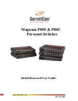
Magnum P80F & P80C Personal Switches                      Installation and User Guide (07/03)


www  GarrettCom  com

.

.

port.  Port  # 2SW always supports fiber ports only and the RJ-45 connector is inoperative at all 

times.  LEDs to indicate operating status of all ports are mounted on the top.  There are power 

(PWR) and ERROR (self-test at power up failed) indicators for the unit. For each port, there are 

Link and Activity (LINK/ACT) LEDs indicating traffic, and speed (ON for 100Mbps), and 

full/half (F/H) duplex indicators.  


The DC power plug connector or “jack” is in the left rear of the chassis. The external 

power supply is 5VDC at either 95 - 125vac at 60 Hz for “-d” models or 120-230vac at 50Hz for 

“-i” models that have IEC power cable connector in the external power supply housing.


2.2.2 

Magnum P80C chassis with all RJ-45 Copper ports 

The Magnum P80C chassis houses one main PC board.  The power supply unit is 

external.  The front side of the chassis has eight twisted-pair switched ports.  Port 2SW has 

manually-selectable Full-Fixed and Auto-negotiation capability.  See section 4.4.  


LEDs to indicate operating status of all ports are mounted on the top.  There are power 

(PWR) and ERROR (self-test at power up failed) indicators for the unit. For each port, there are  

Link and Activity (LINK/ACT) LEDs indicating traffic, speed (ON for 100Mbps), and full/half 

duplex (F/H is ON for full duplex) indicators.  


The DC power plug connector or “jack” is in the left rear of the chassis, like the 

P80F. The external 5VDC power supply is for either 95 - 125vac at 60 Hz for “-d” models or 

120-230vac at 50Hz for “-i” models that have IEC power cable connector in the external power 

supply housing


2.3 

Up-link Port 1SW for Cascading 

The unit has an up-link Port # 1 or 1SW, located on the left-front side of the Switch. It 

enables the port’s twisted pair cable to cascade to another shared hub or switching hub port.  

(See Section 4.6 for more details about up-link).  Port #1SW is capable of full- and half-duplex 

mode auto-sensing, based on the capability of the connected device.  The up-link feature 

operates the same, whether Port # 1SW is connected to either 100Mbps or 10Mbps devices. 

Tx         

UPLINK

FF

A

=     

2SW

UPLINK

                            3            4              5            6            7             

1SW

Magnum P80

Personal 

PORTS                 1           2            3           4              5            6             7            

Link/Act
Speed

F/

Powe
Erro

GARRET

5VDC, 

Summary of Contents for P80C

Page 1: ...www GarrettCom com Magnum P80F P80C Personal Switches Installation and User Guide 5 00 USD...

Page 2: ...witch are trademarks and Personal Switch is a registered trademark of GarrettCom Inc Important The Magnum P80F P80C Personal Switch contains no user serviceable parts Attempted service by unauthorized...

Page 3: ...diate frequency energy and if not installed and used properly that is in strict accordance with the manufacturer s instructions may cause interference to radio communication It has been tested and fou...

Page 4: ...r ports can be connected in strings Mixed Media Fiber Hub 16 port Stackable 10 100 auto sensing Dual Speed 8 port and 16 port Stackables 10 100 auto sensing Stackable Hubs SNMP Optional 10Mb series an...

Page 5: ...onnecting Fiber Optic ST Type Snap In 16 3 2 4 Connecting Fiber Optic Single mode 16 3 2 5 Power budget Calculation for P80F Fiber media 17 3 2 6 Connecting to NICs which support Auto Negotiation 17 3...

Page 6: ...Latency not including packet time 100 to 10 Mbps 5 s 10 to 100Mbps 5 s Path Delay Value 50 BT on all ports Maximum Ethernet Segment or Domain Lengths 10BASE T Unshielded twisted pair 100 m 328 ft 100...

Page 7: ...r Half Duplex selection on switched Ports 2 or 2SW for Magnum P80F Manual switch selects fiber port for FDX or HDX See Section 4 3 for details Full Fixed or Auto negotiation selection on switched Port...

Page 8: ...Magnum P80F SSC d or i Same as P80F but with single mode SC type fiber connector Magnum P80F SSCL d or i Same as P80F but with single mode Long reach 40Km SC type fiber connector Magnum P80F MTRJ d or...

Page 9: ...o keep the shipping container should you need to ship the unit at a later date To validate the product warranty please complete and return the enclosed Product Registration Card to GarrettCom as soon...

Page 10: ...services to network changes and expansions Top mounted LEDs provide status information on each port The Magnum P80 P80F Personal Switches provide high performance plug and play operation in compact pa...

Page 11: ...on capability See section 4 4 LEDs to indicate operating status of all ports are mounted on the top There are power PWR and ERROR self test at power up failed indicators for the unit For each port the...

Page 12: ...iber port is a switched port and performs as a domain providing a high bandwidth backbone connection no media converter is required and supporting long up to 40km fiber cable distances for installatio...

Page 13: ...peration is that more bandwidth is available for good packets when the traffic load is greatest To minimize the possibility of dropping frames on congested ports each Magnum P80 P80F Personal Switches...

Page 14: ...nds plus the packet time at 10 Mb For 100Mb to 100Mb forwarding the latency is 5 microseconds plus the packet time at 100Mb 2 6 Features and Benefits 100Mb switching services for high performance Ethe...

Page 15: ...rkspace location within reach of a standard AC wall outlet They come in a durable metal enclosure for table top or wall mount There is a choice of external power supplies for either 115vac or 230vac 2...

Page 16: ...than needing an auxiliary media converter unit The 100Mbps traffic does not use the bandwidth of the 10 Mbps domain so overall performance of the network is sustained at the highest possible level Exa...

Page 17: ...ility devices such as print servers run at 10 Mbps High performance users need a high bandwidth up link for access to a central LAN and central file servers Any attached node can change speed at any t...

Page 18: ...0C site The rugged metal case of the Magnum P80F P80C will normally protect it from accidental damage in a lab or workplace setting Maintain an open view of the top surface to visually monitor the sta...

Page 19: ...used In either case the maximum distance for unshielded twisted pair cabling is 100 meters 328 ft For fiber port 100BASE FX multi mode 50 125 or 62 5 125 microns cabling can be used whereas for single...

Page 20: ...d using color bands at regular intervals you must use the color coded strand on the associated ports at each end of the fiber optic segment 3 Connect the Transmit TX port light colored post on the Mag...

Page 21: ...to network designers and installers Fiber Port Module Speed Std Mode Std km fdx hdx Wave length nm Cable Size m X mitr Output PT dB R cvr Sens PR dB Worst OPB dB Worst distance Km fdx typical OPB dB t...

Page 22: ...th each unit The small DC power cord from the power supply plugs into the matching rear power jack of the P80F and P80C Personal switchess When the power is applied the green PWR LED will illuminate E...

Page 23: ...iguration settings are user options for UP LINK on RJ 45 port 1 Half Full duplex mode selection for the switched fiber port and FF AN can be done through a switch accessed from the front of the unit f...

Page 24: ...ps speed When the LINK ACT LED is ON steady ON indicates LINK with no traffic blinking ON indicates the port is transmitting receiving The port has auto negotiated for operation If a P80F or P80C RJ 4...

Page 25: ...Cascaded connections may be operated at either 10 or 100Mbps speed The P80F even supports cascaded connections of both 10 Mbps and 100Mbps at the same time on different ports When attaching a 10 Mbps...

Page 26: ...llation Section of the applicable chapter of this manual Also check to make sure that the various components of the network are interoperable 2 Check the cables and connectors to ensure that they have...

Page 27: ...rence of the problem Any changes to system administration procedures should all be noted in this record 5 3 Return Material Authorization RMA Procedure All returns for repair must be accompanied by a...

Page 28: ...hipping container 3 GarrettCom is not responsible for your return shipping charges 4 Ship the package to GarrettCom Inc 47823 Westinghouse Dr Fremont CA 94539 Attn Customer Service APPENDIX A WARRANTY...

Reviews: