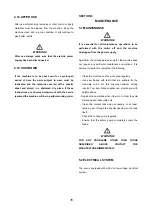
WARNING!
Ensure the blade teeth rotate in the correct direction
(see the arrow on the flywheel safety guard—Fig.6)
·
Tighten the band by means of the special handwheel
(3 Fig.10);
·
Close the flywheel safety guard and secure it with the
special clamps.
WARNING!
Ensure that the microswitch located under the
handwheel is pressed by the stop (1 fig.7) on the
handwheel otherwise the machine will not function.
The band is perfectly tensioned when the microswitch
is pressed by the stop of the handwheel. If the
flywheel safety guard is not properly closed the
machine does not work because of the safety
microswitch. (1 Fig.8)
THIS OPERATION MUST BE CARRIED OUT WHEN
THE MACHINE BOW IS IN STANDBY POSITION AND
THE SAW BLADE IS AT A STANDSTILL. DISCONNECT
THE MACHINE.
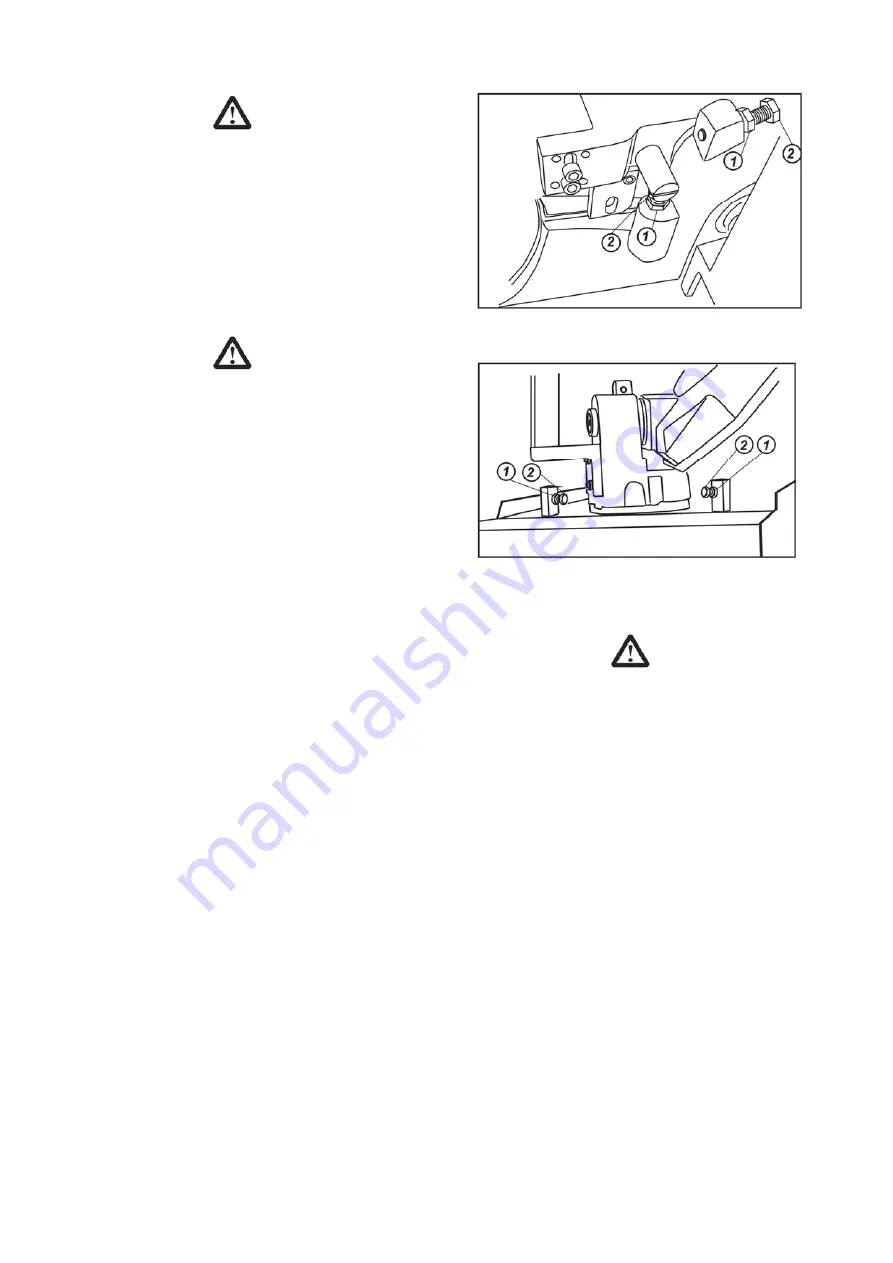
4.10 ADJUSTING THE BOW RETURN STROKE
It is possible to adjust the bow return stroke (this is a
useful operation if several repeated cuts are needed), in
this way the complete return stroke for each single cut be
avoided.
Proceed as follows:
·
Release the hex nut (1 Fig.11).
·
Screw in or out the hex bolt (2 Fig.11) to adjust.
·
Then tighten the hex nut.
Now the bow return stroke will stop at the set position.
4.11 ADJUSTING THE BOW PIVOT STROKE
The bow can pivots from 0
o
to 60
o
. To adjust the 0
o
and
60
o
, proceed as follows:
·
Release the hex nut (1 Fig.12).
·
Screw in or out the hex bolt (2 Fig.12) to adjust.
·
Then tighten the hex nut.
15
Fig.11
Fig.12
4.12 ADJUSTING THE FRONT BLADE GUIDE UNIT
WARNING!
This adjustment must be repeated every time the
section of the workpiece changes.
To get the maximum accuracy and safety during the cut
(i.e with a very small portion of blade not covered by the
guard) the blade guide unit must be as possible to the
piece to be cut.
Release the blade guide arm by operating the piece to be cut.
This way the arm will not make contact with the piece
during its stroke; then retighten the arm.
4.13 STOP THE SAW
To stop the saw band from rotating while operating simple
release the handgrip control (1 Fig.1).
The machine can also be brought to a stop by pushing the
emergency (6 Fig.1).
The machine can also be brought to a stop by turning the
total switch (8 Fig.1) to position “OFF” (or “0” ).
The machine can also stop when the cut I completed.
Summary of Contents for BS260
Page 5: ...4...
Page 6: ...5...
Page 18: ...17...
Page 22: ...21...
Page 23: ...22...
Page 24: ...23...
Page 25: ...24...
Page 26: ...25...
Page 27: ...NOTES Page 27...
Page 28: ...Distributed by Garrick Herbert Pty Ltd KIRRAWEE NSW Australia www garrickherbert com au...


