background image

SECTION 2 

SAFETY REGULATIONS 


2.1 SAFETY


The user must provide instruction for the personnel involved in 

running the machine regarding accident hazards, the safety 

devices provided for the operator and the general accident 

prevention guideline set ort in the directives and legislations of 

the country in which the machine is used. 

Operator safety is one of the main concerns of machine 

designers and manufacturers. During the conception of a mew 

machine, the aim is to foresee all possible hazardous 

situations and, of course, to adopt the suitable protective 

measures. The number of accidents caused by careless and 

clumsy use of the various machines however remains 

extremely high. 

Lack of concentration, carelessness and over-confidence, as 

will as tiredness and sleepiness, are often the direct causes of 

accidents. 

It is therefore recommended to read this manual, and 

particularly the safety regulations, extremely carefully, paying 

specific attention to the particularly dangerous operations. 


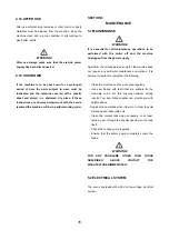
DANGER! 

The Manufacturer declines all responsibility for failure to 

observe the safety and accident prevention regulations 

set out by the legislation in the country where the 

machine is used and described in the following pages. 


Pay attention to the danger sign used in this manual. 

It always precedes warnings of potential danger


THESE DANGERS CAN BE OF THREE LWVELS: 


DANGER! 

Signals maximum danger and warns that the operations 

concerned, if not correctly performed, Cause serious 

injuries, death or long tern health risks. 


WARNING! 

The “WARNING” signal indicates that the operations 


Concerned, if not correctly performed, may cause 

serious injuries, death or long term health risks. 


CAUTION! 

This sign warns that the operations concerned, if not 

correctly performed, may result in damage to the 

machine or to persons. 


2.1.1 TERMINOLOGY USE 


For a more detailed description of the various danger 

levels, there follows a description of a number of 

situations, and specific definitions, which could 

directly involve the machine and /or persons. 


·

 USER: The user is the person, body or company 

that has bought or rented the machine and intends 

using it for those purposed for which it was 

designed. The user is responsible for the machine 

and the training of all the personnel involved in 

running the machine. 

·

  DANGER ZONE: Any area inside and/or close to the 

machine in which the presence of an exposed 

person represents a danger for the safety and 

health of that person. 

·

 Exposed person: Any person found entirely or 

partially in a danger zone. 

·

 OPERATOR: The person or appointed to install, 

operate, adjust, maintain, clean, repair and 

transport the machine. 

·

  SPECIALIZED PERSONNEL: Understood to be those 

persons specifically trained and able to perform 

maintenance or repair interventions which require a 

particular knowledge of the machine, its function, the 

safety elements, the intervention procedures and 

who are able to recognize and avoid the dangers 

resulting from use of the machine. 

·

AUTHORIZED ASSISTANCE CENTRE: The 

authorized assistance centre is the structure, 

legally authorized by the manufacturing company, 

which has specialized and able personnel 

available for carrying out all the necessary 

assistance operations, maintenance and repairs, 

even of a complex nature, for maintaining the 

machine in perfect working order. 


Summary of Contents for BS260

Page 1: ...METAL CUTTING BAND SAW Model BS260 INSTRUCTION MANUAL For your safety read all instructions carefully This product carries the following approvals CE GS CSA and CU L ISO 9001 2008 Certified...

Page 2: ...dling P9 3 2 Installation P10 3 3 General controls P11 SECTION 4 INSTRUCTIONS FOR USE P12 4 1Before use P12 4 2 Use P12 4 3 Operation P12 4 4 Control P12 4 5 Normal cutting P13 4 6 Mitre cutting P13 4...

Page 3: ...to all personnel involved in running the machine It is the responsibility of the personnel involved in running the machine to ensure that the manual is kept intact for the entire life of the machine I...

Page 4: ...ermined in accordance with the standard EN ISO 3746 acoustics with the following results Average equivalent level determined by sound pressure LpAm dB A 67 8 Sound power level LwA dB A 84 7 Continuous...

Page 5: ...4...

Page 6: ...5...

Page 7: ...tes that the operations 6 Concerned if not correctly performed may cause serious injuries death or long term health risks CAUTION This sign warns that the operations concerned if not correctly perform...

Page 8: ...s and or instructions Dispose of any remaining packaging in the appropriate waste recycling or disposal containers When the machine is dismantled follow the a nti pollution guidelines of the country i...

Page 9: ...onnected Should the machine exceed the acoustic pressure level of 85 dB suitable protections such as headphones must be used to protect the hearing Do not expose the machine to rain or use it in damp...

Page 10: ...hine 9 DANGER The lifting and transporting operations can be extremely dangerous if not carried out with maximum caution Move all unqualified personnel away from the area Clean clear and close off the...

Page 11: ...eans of the two holes 15 Fig 1 to a special structure capable of supporting the weight of the machine and any unbalancing created when using it WARNING The Manufacturing Company declines any responsib...

Page 12: ...is working correctly that the safety devices are perfectly operational and that the blade slides smoothly Check that there are mo damaged elements that all the parts have been assembled correctly and...

Page 13: ...tion handgrip control 7 1 Fig 1 press the button 2 Fig 1 Turning the option switch to position main switch 7 1 Fig 1 press the main switch 7 Fig 1 Stop To stop the band saw 12 Push the Emergency red m...

Page 14: ...sufficient quantity during the cutting operations The blade must be well lubricated WARNING The machine is equipped with a low voltage electrical system 24V with a minimum voltage and thermal protect...

Page 15: ...imum band tension adjustment operate as follows Turn the handwheel 23 fig 1 until the stop rests against the microswitch located immediately below the handwheel support flange 1 fig 7 Press the push b...

Page 16: ...the hex nut 1 Fig 11 Screw in or out the hex bolt 2 Fig 11 to adjust Then tighten the hex nut Now the bow return stroke will stop at the set position 4 11 ADJUSTING THE BOW PIVOT STROKE The bow can p...

Page 17: ...ormed with the motor off and the machine unplugged from the power supply Apart from the oil change in gear motor the machine does not require any particular maintenance operations It is however import...

Page 18: ...17...

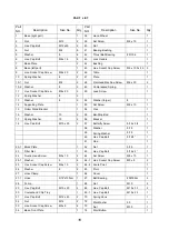
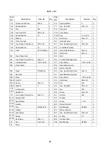
Page 19: ...crew M8 x 10 1 15 Roller Stand Bracket 1 54 Vise 1 16 Washer 10 2 55 Bar Stop Rod 1 17 Spring Washer 10 2 56 Bracket 1 18 Hex Cap Bolt M10 x 20 2 57 Butterfly Screw 5 16 x 3 4 1 58 Washer 5 16 1 59 Sp...

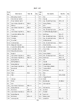
Page 20: ...Cap Screw M6x 8 2 85 H Control Box Panel 1 123 Cover Plate 1 85 H1 Manual Auto Selector 1 127A Slide 1 86 Support 1 127A 1 Spring Washer 10 3 88 Hex Socket Cap Screw M5 x 8 4 127A 2 Hex Socket Cap Sc...

Page 21: ...1 4P x x5 16 1 187 Pipe Fitting 1 4P x x5 16 1 166 Hose Clamp 1 188 Rear Blade Guard 1 189 Blade Guide B 2 168 Hose 5 16 40cm 1 190 Hex Socket Cap Screw M6 x 8 2 169 Saw Arm 1 191 Rear Ball Bearing S...

Page 22: ...21...

Page 23: ...22...

Page 24: ...23...

Page 25: ...24...

Page 26: ...25...

Page 27: ...NOTES Page 27...

Page 28: ...Distributed by Garrick Herbert Pty Ltd KIRRAWEE NSW Australia www garrickherbert com au...

Reviews: