background image

Assembly instructions

®

Assembly instructions

5

6

6.1

6

6.2

L

model no.: 046-7247-4

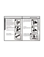
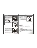
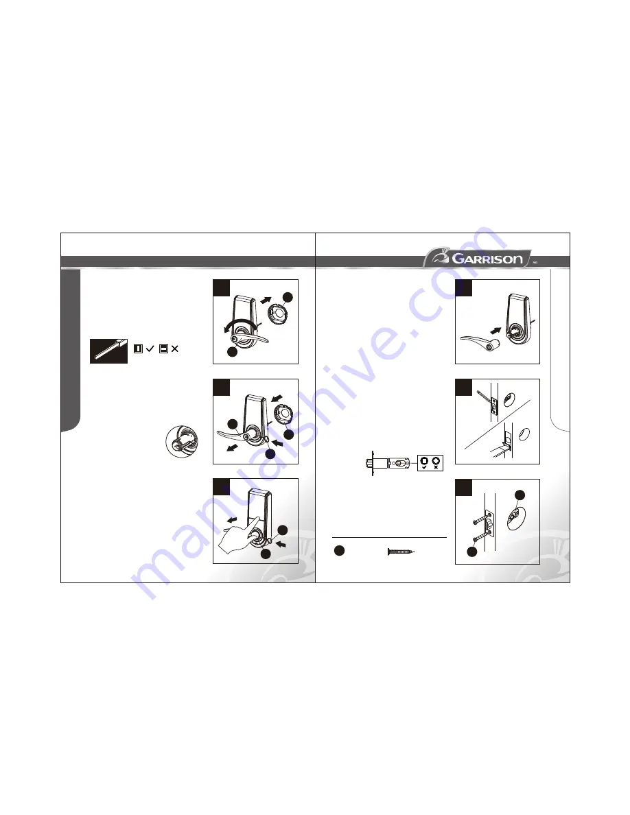
6. Change Lever Handing

Make sure that the lock is unlocked.
(The spindle is 

.) Remove the

protection sleeve (D) of the exterior lock unit.
Rotate the exterior lever (B) by 180 degrees
and return the protection sleeve (D) to its
original position.

vertical

Insert the 

 (L) into the hole

on the neck of the exterior lever (B) and
press down, and pull the lever out at the
same time.

Note that the key cylinder still stays on inside
after the lever is pulled out.

lever removal tool

B

D

The spindle must be vertical.

L

B

D

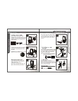
Remove the interior lever

against the lock body while holding and
pulling the lever back.
Insert the 

 (L)

into the hole on the side of the lever, press
down, and the lever can be pulled out. 

Use the thumb and index finger to push

lever removal tool

K

L

Switch interior and exterior levers, then push
in and fasten the levers. Make sure that the
lever is correctly in place, and test the lock
by turning it to make sure it's functioning
properly.

8

7

E

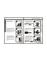
7. Chisel Space for Latch
    Faceplate

Chisel 5/32" (4 mm) deep along

the outline to allow the faceplate to be
aligned with the door edge.
Note: It is not necessary to chisel the door
          edge for the faceplate installation if
          you use the drive-in latch.


Insert the latch and lay the faceplate against
the door edge. Mark the position of faceplate
as a guide.


8. Install Latch

Insert the latch (E) into the door. 
Make sure the cam is on the bottom of the
latch. Use 2 wood screws (L) to secure latch.
Please do not fully tighten the screws until
lock is completely installed.

L

L

Hardware Used

Wood screws                    x2

6.3

Summary of Contents for 046-7247-4

Page 1: ...nual carefully before installing this deadbolt lock and save it for reference ELECTRONIC LEVER WITH TOUCH SCREEN TEMPLATE Fit here on door edge 85x165mm Mark 1 25 4 mm hole at centre of door edge FOR...

Page 2: ...e cam all the way to the right to adjust backset to 2 3 4 70 mm c To restore back to 2 3 8 60 mm push the adjustable sleeve all the way to the left 2 3 8 60 mm Installation Screws Qty 3 M L P Part Des...

Page 3: ...ock with this product on the same door please confirm the backset for the latch and that the specifications for the face plate match Please also refer to the following instructions to adjust the backs...

Page 4: ...de of the lever press down and the lever can be pulled out Use the thumb and index finger to push lever removal tool K L Switch interior and exterior levers then push in and fasten the levers Make sur...

Page 5: ...centre of faceplate a guide 10 Chisel Space for Strike Drill a 1 25 4 mm hole with 1 2 13 mm depth on the centre of strike outline Then use the chisel to out the door frame 1 16 1 6 mm deep within th...

Page 6: ...Used O Wood screw Self tapping screw x1 x1 or 14 2 Install 4 AA alkaline batteries and close the battery cover J Installation is complete Remarks 1 Alkaline batteries are recommended in order to stabi...

Page 7: ...mbers disappear 4 Lock The door can be locked from the inside Code Protection If the user code is entered incorrectly over 5 times the system will initiate the protective function and disable the keyp...

Page 8: ...e is set During this time the door must be locked or unlocked manually with a key 3 Enter PC 5 Automatic lockup Instruction The default setup for the automatic lockup timer is 30 seconds To modify the...

Page 9: ...sponsive No sound and no backlight Issues with batteries or the wiring Replace the batteries or make sure the batteries are installed correctly Please check whether the cable from the interior lock un...

Page 10: ...s PCB board are guaranteed for a period of one 1 year Trileaf Distribution agrees to repair or replace a defective product free of charge within the stated warranty period when returned by the origina...

Reviews: