ANITA ©
11
3.9) Location Detector Assembly and Adjustment
Installing the location detector:
Installing on the servo motor (in-built location detector)
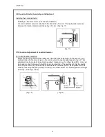
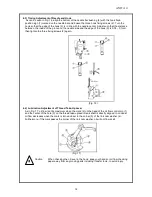
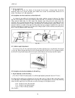
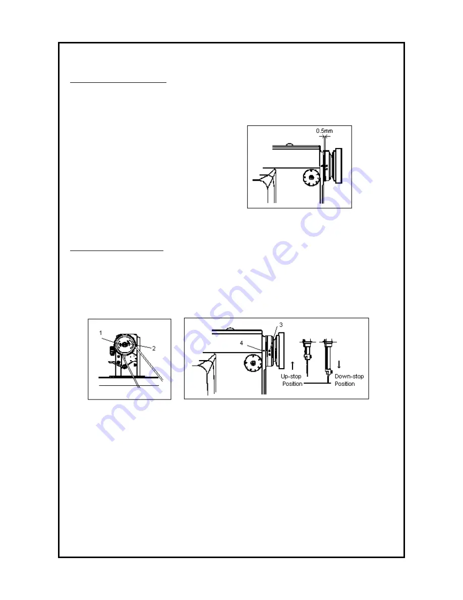
A location detector sensor is attached to the back side of the arm. The appropriate clearance
between the location detector and the pulley is 0,5mm. (See Fig. 11)
(Fig. 11)
3.10) Location Adjustment of Location Detector
For in-built location detectors:
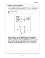
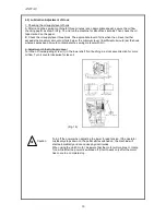
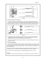
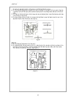
Adjust the up-stop position of the needle such that the white carved sign on the pulley (3) is in
a straight line with the carved sign on the arm (4) when the needle has stopped in the air. That
adjustment can be made by loosening the pulley´s clamp screw (1) on the side with N . U carved
signs and moving it sideways. Adjust the down-stop position of the needle such that the needle
is on the point of moving up when the needle bar is at the lowest point. This adjustment can be
made by loosening the pulley´s clamp screw (2) on the side with N . D carved signs and moving it
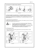
sideways. (See Fig. 12 & 13)
(Fig. 12)
( Fig. 13)
Summary of Contents for GF-1116 Series
Page 30: ...ANITA 30...


