background image

ANITA © 


19 

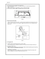
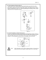
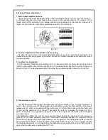
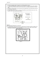
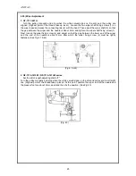
2. Tension adjustment 
    As described in  Fig. 25, the tension of the presser foot will grow  stronger when the tension 
adjusting screw (6) is turned clockwise and weaker when turned counterclockwise. Make sure to 
screw in the fixing nut (1) after adjustment. 
 

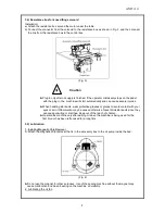
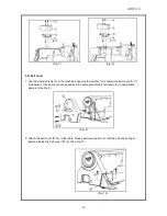
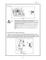
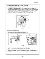
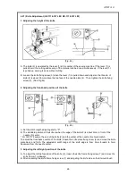
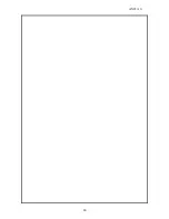
4.10) Adjustment of Automatic Knee-Lifter (Optional) 
 

      An automatic knee-lifter will be attached to the sewing machine at point of delivery. The lifting 
amount of the presser foot when automatically lifting the knee is controlled by the automatic knee-
lifting solenoid shaft crank (1). First, loosen the solenoid cover fixing screw (3) and remove the 
solenoid cover (2). If the solenoid shaft (5) is moved left and the fixing screw (4) is tightened when the 
solenoid crank shaft fixing screw (4) is loose, the lifting amount of the presser foot grows smaller. If the 
solenoid shaft (5) is moved to the right, the lifting amount will grow bigger. Assemble the cover back 
after the adjustment is completed. (The presser foot lifting amount for the automatic knee-lifter will be 
set to 13mm by default at point of delivery). 


(Fig. 26) 


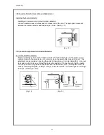
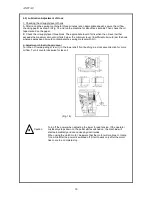
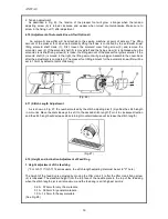
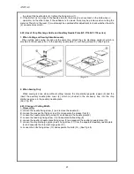
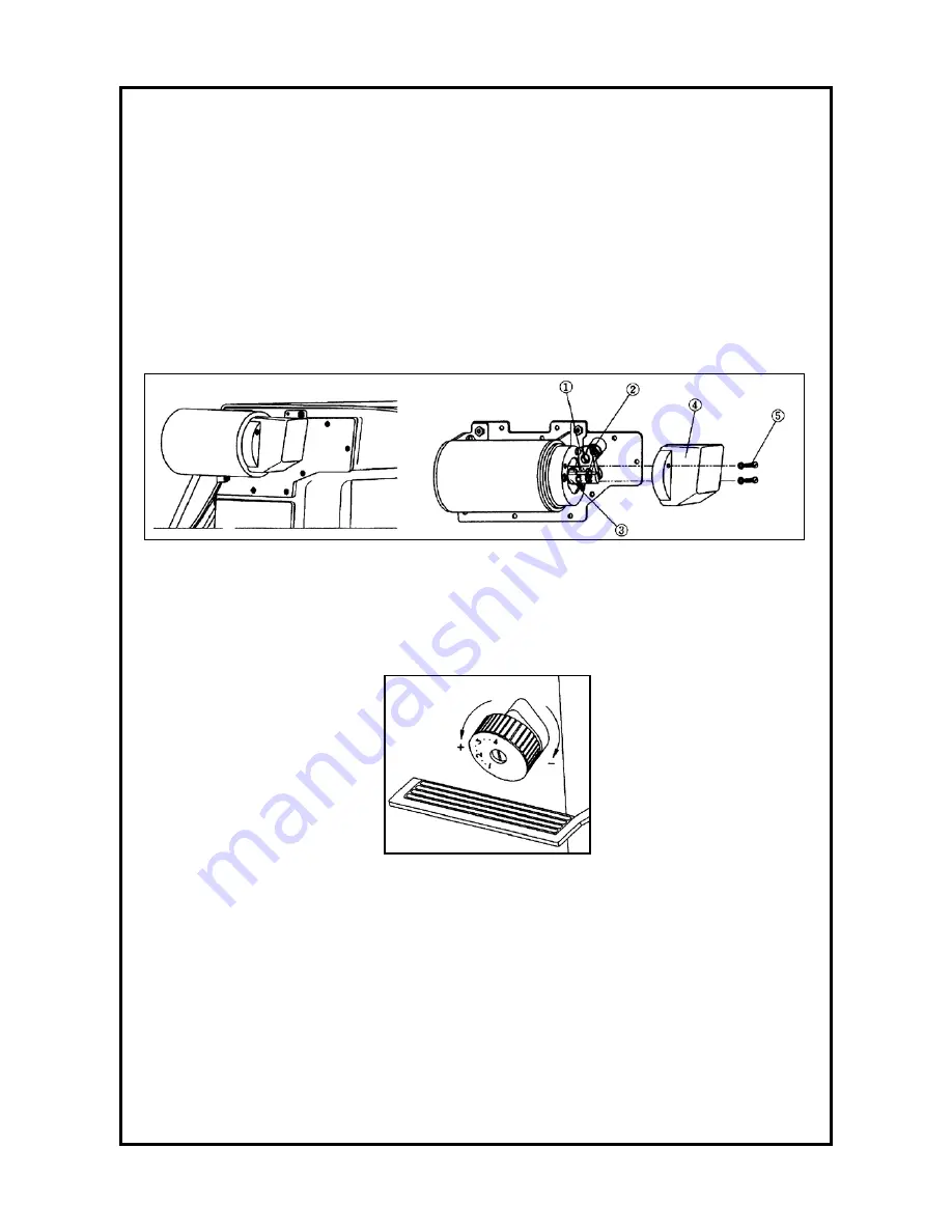
4.11) Stitch Length Adjustment 
 

     As is shown in Fig. 27, the number marked by the stitch adjusting dial (1) signifies the stitch length 
in mm units. Move the dial sideways to set it to the desired stitch length (Turn it in clockwise direction 
and the stitch length will decrease while turning it counterclockwise will increase the stitch length.) 


     (Fig. 27) 


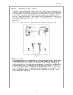
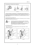
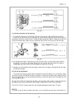
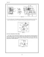
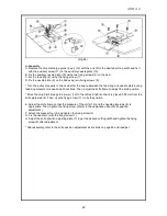
4.12) Height and inclination Adjustment of Feed Dog 


1. Height adjustment of the feed dog  


   (* For  GF-1117/GF-1118 series users, the stitch length adjusting dial must be set to "0" here.) 
 
The height of the feed dog is adjusted by moving the lifter crank (1) after the lifter crank fixing screw 
(2) is loosened. The standard height from the top face of the needle plate to the top of the feed dog 
when the stitch length dial is at its maximum and the feed dog is at its highest point is: 


0,60 ~ 0,70mm for very thin materials, 


0,75 ~ 0,85mm for general materials, 


1,00 ~ 1,20mm for heavy materials. 

(See Fig. 28) 

Summary of Contents for GF-1116 Series

Page 1: ...User s Manual GF 1116 Series GF 1117 Series GF 1118 Series ANITA B s r o Pr myslov 2453 7 680 01 Boskovice Czech Republic tel 420 516 454 774 420 516 453 496 fax 420 516 452 751 e mail info anita cz...

Page 2: ...read take up lever 14 4 5 Lubrication adjustment of hook 15 4 6 Inserting lower thread and tension adjustment 16 4 7 Routing upper thread 16 4 8 Upper thread adjustment 17 4 9 Height and tension adjus...

Page 3: ...3 000 5mm 134R 110 160 5 5 13mm GF 1117 447 H heavy 3 000 5mm 134R 110 160 5 5 13mm GF 1118 143 LM light medium 4 500 5mm 134R 70 110 4 10mm GF 1118 147 LM light medium 4 500 5mm 134R 70 110 4 10mm G...

Page 4: ...a must not This mark means a must for safety This mark means that an electric shock may be caused if the instruction is not followed properly 1 1 Machine mobilization Only personnel with a full unders...

Page 5: ...r sewing textiles and other similar materials Carefully study the following instructions before operating the machine a Read the manual thoroughly and understand the instructions fully before use Caut...

Page 6: ...pressure B When you finish operation always turn off the main switch C During any adjustment repair or needle xchange make sure that the machine is turned off D Make sure that ground connection is pr...

Page 7: ...r hinge 2 Then stand it on the rubber cushions 3 in the four corners See Fig 1 Fig 1 3 3 Chip discharge plate GF 1116 1118 serie Use the chip discharge plate installation guidelines included in the ac...

Page 8: ...ricants wear protective glasses or gloves to avoid contact with your eyes or skin Inflammation may be caused otherwise Never drink lubricants since they can cause vomiting or diarrhea Keep out of the...

Page 9: ...o the belt 4 Tighten the fixed nut 1 first and then tighten the fixed nut 2 to an unmovable position See Fig 6 Fig 6 3 7 Program Unit A Installing automatic knee lifting solenoid on machine head Use f...

Page 10: ...to fasten the belt cover A 1 Installation of the belt cover will be easier if the sewing machine is laid down to an appropriate degree See Fig 9 Fig 9 2 Attach the belt cover B 4 to the table Please...

Page 11: ...the up stop position of the needle such that the white carved sign on the pulley 3 is in a straight line with the carved sign on the arm 4 when the needle has stopped in the air That adjustment can b...

Page 12: ...he explanation about the Adjustment of Location Detector on this page no 11 Fig 14 3 12 Back Tack Button Pressing the back tack button of reverse button 1 during forward sewing will start reverse sewi...

Page 13: ...1 Needle Insertion With the needle groove 1 facing left insert the needle tip into the upper end of the stopper hole 2 and fasten the needle with the clamp screw 3 See Fig 15 Fig 15 4 2 Needle Bar Ad...

Page 14: ...the three fixing screws 2 again Fig 16 4 4 Lubrication Adjustment of Thread Take Up Lever As in Fig 17 oil flow is at its maximum when the mark 2 on the head of the oil flow control pin 1 and the cen...

Page 15: ...oil would jam the hook whereas excessive oil would contaminate the sewing material with oil 2 Adjustment of the Oil Supply Level Turn the oil flow adjusting screw 1 in the lower shaft front bushing i...

Page 16: ...Hold the bobbin case handle 6 and insert it into the hook Pull the handle 6 to remove The bobbin 2 will fall out if the handle is let go See Fig 19 Turn off the power switch when routing the upper th...

Page 17: ...ig 23 The appropriate length of the upper thread remaining after trimming is 30 40mm Fig 23 4 Thread release control The thread release takes place simultaneously with the movement of the trimming sol...

Page 18: ...rform troubleshooting or inspection of the machine For electrical repair or inspection consult with qualified technicians or agent 4 9 Height and Tension Adjustment of Presser Foot 1 As in Fig 25 remo...

Page 19: ...over back after the adjustment is completed The presser foot lifting amount for the automatic knee lifter will be set to 13mm by default at point of delivery Fig 26 4 11 Stitch Length Adjustment As is...

Page 20: ...eed dog as in picture C in Fig 29 C Adjustment of the inclination of the feed dog 3 will result in a change in the height of the feed dog so recheck the height 4 13 Feed Cam Adjustment The timing of t...

Page 21: ...uneven material feed move the feed eccentric cam in the direction of the arrow D To delay the feed timing in order to increase stitch tightness move the feed eccentric cam in the opposite direction f...

Page 22: ...ick material which are susceptible to jams 3 In contrast turning the needle feed connecting rod 2 in b direction would decrease needle movement such that it would be smaller than the feed dog movement...

Page 23: ...xed Blade First loosen the fixed blade tension adjusting nut 1 with a wrench box and then loosen the tension adjusting screw 2 As in Fig 36 adjust the tension adjusting screw of the fixed blade when t...

Page 24: ...knife fixing screw 5 Follow these instructions in reverse order to assemble Fig 38 Fig 39 B If the edge of the fixed blade is worn make sure to grind the knife edge with an oil grindstone as shown in...

Page 25: ...shaft fixing screw 1 Next loosen the wiper fixing screw 4 and adjust so that the gap between the lower end of the wiper and the end of the needle is about 2mm after which the wiper fixing screw 4 must...

Page 26: ...ition of the knife Fig 45 A Set the stitch length adjusting dial to 0 B The standard position of the knife is when the edge of the knife 2 is about 2mm in front of the needle 5 center For GF 1116 seri...

Page 27: ...g 46 Fig 47 2 When Sewing Only When sewing is done alone without cutting remove the chip discharge guide upper 2 and the insert the auxiliary needle plate cover 4 which is provided in the accessory bo...

Page 28: ...the knife frame to adjust the knife position Move the chip discharge guide lower 12 to the left and right so that it is placed 0 05mm from the knife plate side 6 Then use the fixing screw 11 to fix t...

Page 29: ...e and hook Adjust the timing of needle and hook Gap between needle and hook Wrong timing of needle and hook Adjust the timing of needle and hook 3 Stitch skips Remaining length of upper thread Adjust...

Page 30: ...ANITA 30...

Reviews: