ANITA ©
MP00006EN_181206
60
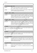
Table 1: Inputs of control board B
Input
Note
I0
Thread break detector, red – connected, green – machine is not connected to detector
I1
Stop button, red – button is pressed, green – button is not pressed
I2
Air pressure detector, red– air pressure is correct, green – air pressure has low level
I3
PC board, red – PC board is switched on
I4
Laser pointer is connected
I5
Left pedal, red – pedal is pressed, green – pedal is in free position
I6
Middle pedal, red – pedal is pressed, green – pedal is in free position or oil level detector for
rotation hook
I7
Right pedal, red – pedal is pressed, green – pedal is in free position
I8
Sensor Z, in bottom an upper position of needle input state is changed
I9
Winding counter sensor
I10
Light curtain A or Pallet sensor (GPS/G), Sensor of presser foot step motor (GPS/H)
I11
Light curtain B or Pallet sensor (GPS/G), Sensor of thread clamp step motor (GPS/H)
Table 2: Outputs of control board B
Input
Note
Q0
Trim
Q1
Wiper
Q2
Winding counter switch off
Q3
Oil injection for rotary hook
Q4
Laser
Q5
PC board switch
Q6
Thread pulling-out
Q7
Help thread tensioner
Q8
Programmable presser foot (only on machines GPS/G)
Q9
Reverse device (flip-flop)
Q10 Needle cooling
Q11 Presser foot (only on machines GPS/G)
Q12 Left/upper feed plate
Q13 Right/bottom feed plate
Q14 Hole-fix
Q15 Thread tensioner
www.garudan.cz
Summary of Contents for GPS/G-10060
Page 69: ......


