background image

© ANITA  

MP03200EN_180822 


15 


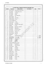
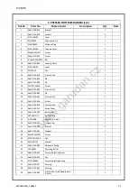
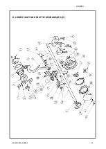
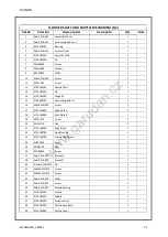
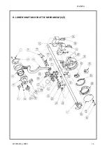
D. LOWER SHAFT AND SHUTTLE MECHANISM (1/2) 

Ref.No 

Parts No. 

Name of parts 

Description 

Qty 

Note 

AnB-3525-842 

Lower Shaft Ass´y 


AnB-3525-872 

Connecting Rod Ass´y 


4710182100 

Bearing 


AnB-3525-911 

Excentric Cam 


4710182000 

Cam Side Plate 


4710183400 

Pin 


ZMJ06006 

Screw 


WA06008 

Washer 


B4406032 

Collar 


10 

M5x6 DIN 913 

Screw 


11 

ZSC11002 

Screw 


12 

4710182200 

Shuttle Shaft 


13 

4710183100 

Pin 


14 

4710182300 

Hinge Pin 


15 

4710183000 

Connecting Rod Pin 


16 

M4x6 DIN 913 

Screw 


17 

4710182800 

Slide Plate A 


18 

4710182900 

Slide Plate B 


19 

ZSD11010 

Screw 


20 

ZSL11002 

Nut 


21 

4710182600 

Slide Block 


22 

4710182700 

Side Block Pin 


23 

4710182500 

Driving Shaft Crank 


24 

ZSB12036 

Scrw 


25 

ZSL18003 

Nut 


26 

ZMJ08003 

Screw 


27 

AnB-3525-810 

Bracket 1 


28 

AnB-3525-809 

Bracket 2 


29 

6-20m6 DIN 6325  Pin 


30 

M6x30 DIN 912 

Screw 


31 

M6x35 DIN 912 

Screw 


32 

AnB-3525-916 

Collar 


33 

M6x6 DIN 913 

Screw 


34 

AnB-3525-827 

Shuttle Bushing 


35 

4710181300 

Shuttle 


36 

4710183200 

Bobbin 


37 

4710184200 

Distance Piece 


38 

4710181400 

Shuttle Race Body 


39 

4710183600 

Shuttle Cover 


www.garudan.cz

Summary of Contents for GPS/X-3525 Series

Page 1: ...User s Manual GPS X 3525 ANITA B s r o Pr myslov 2453 7 680 01 Boskovice Czech Republic tel 420 516 454 774 420 516 453 496 fax 420 516 452 751 e mail info anita cz MP03200EN_180810...

Page 2: ...d Property of Anita B s r o and protected by copyright The use of this content without written permission is prohibited Copyright Anita B s r o 2018 VERSION CREATED ON APPROVED BY MP03200EN_180810 10...

Page 3: ...ar 15 2 Needle to hook relationship 16 3 Adjustment the needle distance from the tip of the hook 16 4 Adjustment of presser foot 17 5 Thread of upper thread 18 6 Opening of the main tensioner discs 19...

Page 4: ...e 29 Stitch length 0 1 40 mm No of needles 794H Nm 160 300 Hook Barrel shuttle hook XL Lift of Presser Foot max Max 20 mm stroke 10 20 mm Lift of feeding frame Standard 35 mm Thread Trimmer Standard M...

Page 5: ...ANITA MP03200EN_180810 5 2 DESCRIPTION Fig 1 w w w g a r u d a n c z...

Page 6: ...g the machine turn off the drive with the on off switch or the main machine switch Before dismantling the machine or maintenance disconnect the power supply by pulling the plug out of the socket If yo...

Page 7: ...equipped with interference suppression filters according to EMC SN 50081 1 and 50081 2 If a current protector is connected to the mains the fault current type and high surge current type e g type S mu...

Page 8: ...ing J Space below the upper pressure frame The compressive force must not exceed 50N This is how the machine is adjusted from production The pressure can be regulated by the auxiliary pressure gauge 2...

Page 9: ...ient storage temperature is from 10 to 60 C D Humidity is between 20 80 relative humidity 5 ELECTRIC DEVICE SETTING A Power voltage The voltage should be within the range of 10 of the formal voltage P...

Page 10: ...east at the beginning of each shift Fig 5a Fig 5b Lubricate the hooks into the holes in the right and left hand holster according to the arrows Fig 5a The channel is lubricated by the track of the hoo...

Page 11: ...er while keeping the needle slot 3 facing tip of the hook then tighten it with the screw 1 see Fig 7 Fig 7 3 Upper threading Lead the thread as the figure 8 shows and put the thread take up lever in u...

Page 12: ...ain of bobbin thread end should be kept about 55mm long Fig 9 5 Insertion of bobbin to bobbin case Insert the threaded bobbin into the tilted bobbin case Drain the thread into the outlet hole in the s...

Page 13: ...e end of needle thread after trimming B Bobbin thread tension adjustment Fig 10 As the figure shows turn screw 1 clockwise to increase the tension while counter clockwise to reduce the tension Fig 11...

Page 14: ...adjust the through hole on the needle axis loosen the presser foot 1 by loosening the screws Rotate the presser foot onto the needle axis and tighten the screws By default the foot is about 1 mm above...

Page 15: ...n alignment with the needle bar Using the adjusting screw 3 on the connecting rod Fig 15 tighten the connecting rod on the main shaft Then turn the hand wheel The driver of the hook on the lower shaft...

Page 16: ...case 1 Fig 18 and thus the hook tip to the desired distance from the needle After losing the screw 2 Fig 18 we move by rotation the eccentric 3 the hook case until the distance from the hook tip to f...

Page 17: ...er with the needle bar or with a little delay see Fig 21 The eccentric 1 is placed on the main shaft 3 see Fig 20 Fig 20 Fig 21 Fig 22 b Set the position of the driver 8 Fig 21 on the presser bar 9 to...

Page 18: ...re of the presser foot is adjusted by pressing the spring 13 This spring can be adjusted after losing nut 14 by turning the screw 15 Summary presser foot 17 should be moving with the delay defined by...

Page 19: ...6 This parameter defines position of the needle at the moment when the tensioner discs are opened The discs are opened during last trimming rotation in order to ensure sufficient length of the upper t...

Page 20: ...Set the position of fixed knife 1 so that its sharp edge is in distance of 8 mm from the center of the needle plate insert 2 c Loosen the screw 4 and set the position of moving knife 3 so that the di...

Page 21: ...ving knifes is taking the needle Default value if 500 ms Parameter 42 turning OFF feed dog operating time of thread feeder it sets the position of needle bar hen the moving knife is cutting the thread...

Page 22: ...nabling sewing operation of the machine Fig 29 10 Setting of bobbin winder Setting amount of Wolf thread Fig 30 a Loosen screws 1 on the stopper lever 3 b Movement of stopper lever 3 in the direction...

Page 23: ...ntral position in both axes Initial point refers to the actual center position of the feeding plate towards the needle In this position the edges of sensor plates 2 and 4 are in line with the middle o...

Page 24: ...of the left 1 and right 2 upper frame down movement can be adjusted by pressure gauges 6 7 see Fig 38 b For disassembly of the upper 2 piece frame remove 12 screws 5 At the same time it is necessary...

Page 25: ...arameter 31 Fig 35 shows valve 3 for adjustment of the amount of air supplied to the cooling nozzle 16 Lock of the feeding clamp The feeding clamp is connected with the X axis movement mechanism by me...

Page 26: ...36 Fig 36 Now you have access to lubricating head 2 on the flange of the bearing 1 see Fig 37 Then apply the lubricant on the bearings by means of manual press Lubrication is recommended to be perfor...

Page 27: ...eck the correct air pressure value on the manometer gauge d Make sure that the liquid in the separator 5 is regularly emptied Notice If the pressure drops below the minimum level the machine displays...

Page 28: ...allet middle pedal is used for pressing down the upper frame and left pedal is used for start of the sewing of selected pattern This setting is described in chart 1 Chart 2 Setting for operation with...

Page 29: ...speed but should not exceed the maximum speed defined for the respective stitch length Straight stitch ZigZag stitch Stitch length mm Spm Stitch length mm Spm Up to 9 800 For example 12x5 Up to 10 700...

Page 30: ...e wiper Wrong position of needle motor sensor or sensor plate Check position of needle motor sensor plate and the sensor function Fault of needle motor or motor driver Exchange motor for needle drivin...

Page 31: ...correct clearance between needle and hook Wrong tension of thread take up spring Adjust correct tension of the spring 7 Wrong function of thread breakage detector Thread take up spring is not well li...

Page 32: ......

Page 33: ...Spare Parts List GPS X 3525 ANITA B s r o Pr myslov 2453 7 680 01 Boskovice Czech Republic tel 420 516 454 774 420 516 453 496 fax 420 516 452 751 e mail info anita cz MP03200EN_180822...

Page 34: ...rty of Anita B s r o and protected by copyright The use of this content without written consent of Anita B s r o is prohibited Copyright Anita B s r o 2018 VERSION CREATED ON APPROVED BY MP03200EN_180...

Page 35: ...and Shuttle Mechanism 2 2 16 E Thread Trimming Mechanism 1 2 18 E Thread Trimming Mechanism 2 2 20 G X Moving Mechanism 1 2 22 G X Moving Mechanism 2 2 24 I Feed Frame Mechanism 1 2 26 I Feed Frame M...

Page 36: ...ANITA MP03200EN_180822 4 A FRAME AND MACHINE BODY PARTS w w w g a r u d a n c z...

Page 37: ...152A Washer 4 12 6 DIN 127A Washer 4 13 AnB 3525 028 Cover 1 14 AnB 3525 063 Cover 1 15 M4x8 DIN 967 Screw 8 16 M5x12 DIN 912 Screw 8 17 A2401507 Stop Switch Bracket 1 18 A2301507 Stop Switch 1 19 M4...

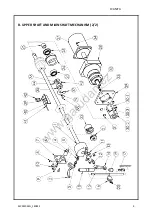
Page 38: ...ANITA MP03200EN_180822 6 B UPPER SHAFT AND MAIN SHAFT MECHANISM 1 2 w w w g a r u d a n c z...

Page 39: ...Rod 1 15 4410140100 Needle Bar 1 16 4410140900 Needle Bar Holder 1 17 4410140200 Needle Clamp 1 18 AnB 3525 820 Bushing 1 19 AnB 3525 808 Bushing 1 20 ZMH16005 Screw 2 21 51202 Ball Bearing axial 1 s...

Page 40: ...MP03200EN_180822 B UPPER SHAFT AND MAIN ANITA UPPER SHAFT AND MAIN SHAFT MECHANISM 2 2 ANITA 8 w w w g a r u d a n c z...

Page 41: ...ISM 2 2 Ref No Parts No Name of parts Description Qty Note 38 M4x10 DIN 84 Screw 2 39 4 DIN 127A Spring washer 4 40 B3006032 Z sensor bracket 1 41 K4001507 Sensor 1 42 M4x12 DIN 912 Screw 2 43 M6x6 DI...

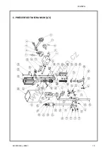
Page 42: ...ANITA MP03200EN_180822 10 C PRESSER FOOT MECHANISM 1 2 w w w g a r u d a n c z...

Page 43: ...AnB 3525 803 Presser Link 1 18 AnB 3525 882 Pin 1 19 AnB 3525 815 Presser Link 1 20 AnB 3525 836 Screw 1 21 AnB 3525 814 Presser Link 1 22 AnB 3525 811 Guide Cube 1 23 AnB 3525 818 Bar Holder 1 24 SKF...

Page 44: ...ANITA MP03200EN_180822 12 C PRESSER FOOT MECHANISM 2 2 w w w g a r u d a n c z...

Page 45: ...Connecting rod 1 45 AnB 3525 918 Pin 1 46 4 DIN 6799 Washer 2 47 AnB 3525 886 Plate 1 48 AnB 3525 885 Strut 3 49 M5 DIN 934 Nut 3 50 AnB 3525 887 Cover 1 52 CQ2B32 50DZ Shim ring 1 53 AS2201F 01 04S...

Page 46: ...ANITA MP03200EN_180822 14 D LOWER SHAFT AND SHUTTLE MECHANISM 1 2 w w w g a r u d a n c z...

Page 47: ...83000 Connecting Rod Pin 1 16 M4x6 DIN 913 Screw 2 17 4710182800 Slide Plate A 1 18 4710182900 Slide Plate B 1 19 ZSD11010 Screw 2 20 ZSL11002 Nut 2 21 4710182600 Slide Block 1 22 4710182700 Side Bloc...

Page 48: ...ANITA MP03200EN_180822 16 D LOWER SHAFT AND SHUTTLE MECHANISM 2 2 w w w g a r u d a n c z...

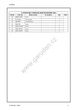
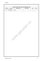
Page 49: ...ANITA MP03200EN_180822 17 D LOWER SHAFT AND SHUTTLE MECHANISM 2 2 Ref No Parts No Name of parts Description Qty Note 40 AnB 3525 912 Screw 2 41 4710183800 Spring 2 w w w g a r u d a n c z...

Page 50: ...ANITA MP03200EN_180822 18 E THREAD TRIMMING MECHANISM 1 2 w w w g a r u d a n c z...

Page 51: ...mm 1 14 AnB 3525 831 Spring 1 15 E9426032 Plate 1 16 M4x8 DIN 912 Screw 1 17 M4x8 DIN 965A Screw 1 19 AnB 3525 823 Pin 1 20 AnB 3525 901 Washer 1 21 J4741507 Washer 0 4 mm 1 22 J4751507 Washer 0 5 mm...

Page 52: ...MP03200EN_180822 E THREAD TRIMMING MECH ANITA THREAD TRIMMING MECHANISM 2 2 ANITA 20 w w w g a r u d a n c z...

Page 53: ...E THREAD TRIMMING MECHANISM 2 2 Ref No Parts No Name of parts Description Qty Note 41 M5x12 DIN 912 Screw 4 42 M5x45 DIN 912 Screw 2 43 5 DIN 125A Washer 2 44 M6x14 DIN 912 Screw 2 45 6 DIN 125A Washe...

Page 54: ...ANITA MP03200EN_180822 22 G X MOVING MECHANISM 1 2 w w w g a r u d a n c z...

Page 55: ...sor Bracket 1 16 AnB 3525 012 X Sensor Plate 1 17 AnB 3525 005 X Sensor Plate 1 18 K4001507 X Sensor 1 19 G1903525 Linear Motion X 1 20 G2003525 Railway of Linear Guide 6 21 GX F8A Y Sensor 1 22 G0213...

Page 56: ...ANITA MP03200EN_180822 24 G X MOVING MECHANISM 2 2 w w w g a r u d a n c z...

Page 57: ...5 M4x8 Screw 16 49 AnB 3525 024N Bracket 8 50 DIN 125 A4 Washer 3 51 DIN 934 M8 Nut 1 52 DIN 913 M5x8 Screw 2 53 DIN 6885 A5x5x20 Tongue 1 54 DIN 965A M4x8 Screw 3 55 DIN 125 A10 Washer 4 56 DIN 125 A...

Page 58: ...ANITA MP03200EN_180822 26 I FEED FRAME MECHANISM 1 2 w w w g a r u d a n c z...

Page 59: ...ailway of Linear Guide 2 15 S4383525 Linear motion X 2 16 S4363525 Holder 2 17 S4453525 Screw pin 2 18 S4423525 Rod end bearing 2 19 S4323525 Lever 2 20 S4403525 Holder 2 21 CQ2B20 30D Air cylinder 2...

Page 60: ...ANITA MP03200EN_180822 28 I FEED FRAME MECHANISM 2 2 w w w g a r u d a n c z...

Page 61: ...ANITA MP03200EN_180822 29 I FEED FRAME MECHANISM 2 2 Ref No Parts No Name of parts Description Qty Note 40 5 DIN 125A Washer 2 41 AnB 3525 927 Screw pin 2 w w w g a r u d a n c z...

Page 62: ...ANITA MP03200EN_180822 30 I2 FEED FRAME FOR CUSTOMER DESIGN w w w g a r u d a n c z...

Page 63: ...te 1 I3006032 Block stopper 2 2 I2806032 Bracket 2 3 AnB 3525 867 Holder 2 4 CQ2B12 20DM Pneumatic cylinder 2 5 KQ2H04 M5 Hose nipple 4 6 I3106032 Knuckle pin 2 7 M4x12 DIN 912 Screw 16 8 M3x35 DIN 91...

Page 64: ...ANITA MP03200EN_180822 32 J THREAD TENSION MECHANISM w w w g a r u d a n c z...

Page 65: ...ion Adjusting Ass y 1 9 5 DIN 125A Washer 1 10 M5x12 DIN 912 Screw 1 11 AnB 003 151 Holder 1 12 M3x8 ISO 7046 Screw 2 13 AnB 3525 856 Holder 1 14 CJP2B10 25D Pneumatic Cylinder 1 15 AnB 3525 873 Threa...

Page 66: ...ANITA MP03200EN_180822 34 K BOBBIN WINDER AND HAND PULLEY w w w g a r u d a n c z...

Page 67: ...2 6 M5x6 DIN 913 Screw 4 7 D0301507 Spring 1 8 AnB 3525 905 Bushing 1 9 AnB 3525 906 Pin 1 10 4710320500 Friction Wheel 1 11 4710320805 Bobbin Winder 1 12 AnB 3525 870 Extension 1 13 4710321300 O ring...

Page 68: ...ANITA MP03200EN_180822 36 L STAND AND TABLE w w w g a r u d a n c z...

Page 69: ...5 314 Support 2 16 AnB 3525 315 Plate 2 17 L0803525 Screw 4 19 A10 DIN 127 Spring Washer 8 20 M10 DIN 9021 Washer 4 21 M10 DIN 934 Nut 8 22 AnB 3525 048 Holder 4 23 S0206032 Holder 8 24 M5x10 DIN 912...

Page 70: ...ANITA MP03200EN_180822 38 M LUBRICATION PARTS w w w g a r u d a n c z...

Page 71: ...2 Lubrication Felt 1 16 M1606032 Lubrication Plate 1 17 M1706032 Lubrication Felt 1 18 M5x8 DIN 7984 Screw 3 19 A5 3 DIN 125 Washer 1 20 M2006032 Lubrication Plate 1 21 M2106032 Oil Observator Complet...

Page 72: ...ANITA MP03200EN_180822 40 N AIR CONTROL PARTS w w w g a r u d a n c z...

Page 73: ...9 U0401507 Clutch 3 10 U0831507 Plate 2 Standard 11 TV25110 06 Magnetic Valve 8 Standard 12 U1001507 Plug 1 13 U0901507 Silencer 4 14 U1201507 Clutch 14 15 U1401507 Screw 8 16 PC6 01 Clutch 2 17 U0601...

Page 74: ...ANITA MP03200EN_180822 42 Q OPERATION UNIT AND THREAD STAND w w w g a r u d a n c z...

Page 75: ...me of parts Description Qty Note 1 O2201507 Holder LCD 1 2 O2101507 Touch LCD 15 1 3 M8x20 DIN 912 Screw 1 4 M8x50 DIN 912 Screw 4 5 A8 4 DIN 125 Washer 4 6 A8 DIN 127 Spring Washer 4 7 M8 DIN 934 Nut...

Page 76: ...ANITA MP03200EN_180822 44 R CONTROL BOX w w w g a r u d a n c z...

Page 77: ...4 C6461510 Drive for Motor of Axis Z 1 5 R3201507 Power Supply ATX 1 6 R3081507 PC module G 1 7 LRS 150 24 Switch mode Power Supply 1 10 R1001507 Master Switch 1 11 R1101507 Circuit Breaker 1 12 R1201...

Page 78: ...ANITA MP03200EN_180822 46 S OPTION w w w g a r u d a n c z...

Page 79: ...4 5 3 DIN 125A Washer 2 5 M5X8 DIN 912 Screw 1 6 KN Q06 100 Jet 1 7 KQ2H04 06 Hose nipple 1 8 NC0106032 Ring 1 9 S1806032 Holder of cooling needle 1 10 AS2001F 04 Choke 1 11 M3x8 DIN 912 Screw 1 12 MS...

Reviews: