background image

                                                                                                                                    © ANITA 

MP02800EN_180319 

14 

4.9 BACKTACKING (REVERSE FEED; CLOSING UP) 


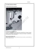
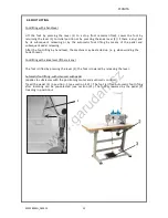
Backtacking with a hand lever (applies to manually controlled  subclasses) 


Press  the  lever  (1)  downwards.  The  machine  will  feed  in  the  reverse  direction  until 

you release the lever. 


Backtacking with a microswitch (applies to automatically controlled  subclasses) 

Press the microswitch (2). The machine will backtack until you  release the grip.


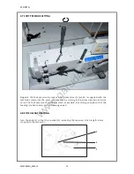
Automatic backtacking (bar sewing, bartacking) 
On  machines  equipped  with  the  positioning  motor  and  automatic  control  the  automatic 

backtacking can be pre-selected with a pre-selected number of reverse stitches both at the 

beginning and at  the end of the seam. At the beginning of the seam (after previous  thread 

trimming) after the pedal treading forwards the machine will sew  the pre-selected bar and 

continue  the  sewing.  At the  end  of  the  seam  it  will sew  the pre-selected  bar at  the pedal 

treading in position 

-2 (see section 4.11). 


www.garudan.cz

Summary of Contents for GZ-5527-443

Page 1: ...User s Manual GZ 5527 443 GZ 5527 447 ANITA B s r o Průmyslová 2453 7 680 01 Boskovice Czech Republic tel 420 516 454 774 420 516 453 496 fax 420 516 452 751 e mail info anita cz MP02800EN_180319 ...

Page 2: ...EN_180319 2 All rights reserved Property of Anita B s r o and protected by copyright The use of this content without written consent of Anita B s r o is prohibited Copyright Anita B s r o 2018 w w w g a r u d a n c z ...

Page 3: ... NEEDLE SYSTEM 134 10 4 5 2 MACHINE 527I NEEDLE SYSTEM 134 134 35 10 4 6 FOOT LIFTING 12 4 7 FOOT PRESSURE SETTING 13 4 8 STITCH LENGTH SETTING 13 4 9 BACKTACKING REVERSE FEED CLOSING UP 14 4 10 SETTING OF ZIG ZAG STITCH WIDTH THROW AND POSITION 15 4 11 CONTROL OF MACHINE EQUIPPED WITH POSITIONING MOTOR AND SOLENOID AUTOMATIC CONTROL 16 4 11 1 CONTROL PANEL 16 4 11 2 KEY CONTROL PANEL 17 4 12 THRE...

Page 4: ...ons and alterations to the machine may only be carried out under observance of all the relevant safety regulations Only spare parts which have been approved by us are to be used for repairs We expressly point out that any replacement parts or accessories which are not supplied by us have not been tested and approved by us The installation and or use of any such products can lead to negative change...

Page 5: ...ouble thread zig zag lockstitch It has a bi directional drop feed The machine is equipped with a horizontal hook Wick lubrication There is an automatic bobbin winder on the machine arm 4 MACHINE OPARATION 4 1 NEEDLE THREADING Do the threading according to pictures w w w g a r u d a n c z ...

Page 6: ...hreading according to picture A wind 5 times round the bobbin Push the lever 2 in the arrow direction 3 Start the machine up After the bobbin winding release the lever 2 remove the bobin and fix another bobbin immediately and prepare its winding during the sewing A B w w w g a r u d a n c z ...

Page 7: ...d end 4 oriented according to the picture 2 Draw the thread end 4 through the slit 5 pull under the spring 6 and pull into the slit 7 Pull out the theads 4 2 3 cm from the bobbin case and insert the case 2 back in the hook and press it down in the arrow direction 8 till the lock inside the case clicks and secures it against falling out 8 2 1 6 5 2 3 4 2 7 w w w g a r u d a n c z ...

Page 8: ...sion as possible but high enough so as the thread cannot be pulled out from the tensioner 1 at the material removing after previous trimming when the tensioner 2 is opened switched off The tensioner 1 is never switched off Main tensioner adjustment 2 Regulate the thread tension with the tensioner 2 until you achieve a good interlacing of the threads see below w w w g a r u d a n c z ...

Page 9: ...imming 2 Bobbin braking should be as small as possible because it causes difference of tensions of full and empty bobbin and subsequently of thread interlacing in the stitch defective look of the seam Regulate the bobbin braking with a screw 7 and watch the bobbin unwinding after the thread trimming remove the case 3 from the machine grip it so that the bobbin cannot turn and pull out the thread e...

Page 10: ... 3 is oriented according to detail D Tighten the screw 1 4 5 2 Machine 527i needle system 134 134 35 Loosen the screw 1 and remove the needle 2 Fix a new needle 134 according to fig B Loosen the screw 4 and fix a new needle 134 35 according to fig C The needle turn it so that the needle scarf 3 is oriented according to detail D Tighten the screw 1 1 C 3 2 1 2 3 4 4 B D w w w g a r u d a n c z ...

Page 11: ... MP02800EN_180319 11 Loosen screw 1 according to picture A and adjust the needle bar so that in position 0 according to picture B the tip of the hook is 0 5 mm above the needle eye A B w w w g a r u d a n c z ...

Page 12: ...er the foot lifting by hand lever the machine may be started up e g when winding the hook thread Foot lifting with a knee lever if there is any The foot is lifted by pressing the lever 2 the foot is lowered by releasing the lever Automatic foot lifting with solenoid with pedal applies to subclasses with the positioning motor and automatic control Tread the pedal 3 in position 1 see section 4 11 Th...

Page 13: ...he pressure increases by turning in the arrow direction and vice versa The foot pressure should be as small as possible but strong enough so that the feeding is reliable even at a high sewing speed 4 8 STITCH LENGTH SETTING Turn the knob 1 so that the number 2 indicating the required stitch length in mm is opposite the screw 3 3 2 1 w w w g a r u d a n c z ...

Page 14: ...til you release the grip Automatic backtacking bar sewing bartacking On machines equipped with the positioning motor and automatic control the automatic backtacking can be pre selected with a pre selected number of reverse stitches both at the beginning and at the end of the seam At the beginning of the seam after previous thread trimming after the pedal treading forwards the machine will sew the ...

Page 15: ...tch position Press the lever 1 in the arrow direction A until it strikes the lever 2 The lever arrest is released 3 Make sure that the lever setting does not change at the arrest switching off 2 Press the lever 3 and turn it at the same time up to the stop inside the machine against the respective symbol indicating the zig zag stitch position Only the middle position of the lever is arrested with ...

Page 16: ...or foot lifting 0 Neutral position See note 1 Slightly forwards Command for foot lowering 2 Further forwards Sewing at minimum speed 1gear 3 Further forwards Sewing 2 speed gear 13 Fully forwards Sewing at maximum speed 12 gear Note The needle position can be pre selected for the neutral position needle down up as well as for the foot position down up at the seam stop by putting the pedal in the n...

Page 17: ...and backtacking When the key is pressed at sewing the sewn material is fed backwards 2 2 Needle positioning in upper or bottom position By the parameter the key function can be defined 1 needle up down 2 needle up 3 one stitch factory setting is 1 w w w g a r u d a n c z ...

Page 18: ...knife Mount the bolt 2 back again 4 12 2 TRIMMING LEVER Thr trimming lever 6 should be located as high as possible but it should not rub the plate 5 The eccentric bolt 2 groove should be in horizontal position Tilt the machine loosen the screw 3 and turn the eccentric bolt 4 so that the lever does not rub 6 the plate 5 however it should be positioned as high as possible Tighten the screw 3 Loosen ...

Page 19: ... unnecessary oil out of the hook at the machine high speed operation Check of oil reserve in oil tanks see section 10 2 1 week Cleaning of mechanisms in the base plate Cleaning vacuuming wiping out 1 month oil tray Cleaning of ventilator grid on the motor 1 month Check of bobbin case 4 fitting clearance in the hook housing 5 Check of drive V belt tension checking method is described in the second ...

Page 20: ...oil into tank 3 through the hole 4 at least once two weeks until the oil starts flowing from the terminal 5 Add several drops of oil in holes 6 and 7 once a month Grease lubrication Add grease in grease cups 8 and 9 by means of a lubrication press once a year 1 2 6 3 5 8 9 w w w g a r u d a n c z ...

Page 21: ......

Reviews: