9
|
GARY FISHER SERVICE INFORMATION
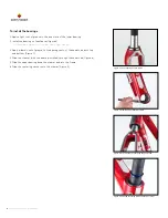
To install the shims, bearing cover, and spacers
Fisher installs three 1mm shims between the centering washer and the bearing cover
to ensure an adequate space between the bearing cover and the top of the head tube.
There should be at least 0.5 millimeter space to prevent contact or interference.
1. Slide the three shims onto the steerer.
2. Slide the bearing cover onto the steerer (Figure 10).
3. Measure the gap between the head tube and the bearing cover.
+
In some cases, all three shims may provide more clearance than necessary. In this case, remove
shims until there is only one millimeter of space between the head tube and the bearing cover
(Figure 11).
4. Slide the headset spacers and the stem onto the steerer.
5. Install the headset top cap and adjusting bolt.
+
For a carbon steerer, do not use a star-fangled nut. Use the special adjusting plug.
6. Adjust the headset.
+
The Cronus headset uses an angular contact bearing system, so the headset will rotate
freely with a wide range of tension. Make sure there is no free play, but do not overtighten
the bearings because they might wear prematurely.
7. Tighten the stem clamp bolts to the manufacturer’s recommendation.
8. Follow the steps in “Inspecting the Headset.”
inspecting the Headset
Once a month inspect the headset of your bicycle to see that it is not loose, nor too
tight. If your headset bearings are loose or too tight, do not ride the bicycle.
Readjust the bearings or take your bike to your Gary Fisher dealer for service.
To check is the headset is too loose
1. Stand over the top tube of your bicycle with both feet on the ground.
2. Apply the front brake firmly while you rock the bicycle forward and backward.
3. Look, listen, and feel for looseness of the headset bearings.
To check is the headset is too tight
1. With the front wheel off the ground, slowly rotate the fork and handlebar to the
right and left.
2. Look, listen, and feel for any grinding noises, or stickiness or binding at any point
in the rotation.
figure 11. measure the distance from the head tube to the
bearing cover
figure 10. the bearing cover and one spacer on
the steerer


