background image

Multi Gas Clip Simple Plus User’s Manual

UM MGC-S-PLUS v1.00a 

Portable gas detectors you can count on

12 of 18

Calibration 

The detector can be configured to keep track of regular calibration intervals in a Calibration Log. The interval can be set 

using the GCT IR-Link software. When a calibration comes due, or if the last calibration has failed, then the detector’s 

display will continually flash “CAL DUE” until the detector has been successfully calibrated. Performing a calibration that 

will be recorded in the Calibration Log can be done either automatically (insert the detector into the MGC Simple Clip 

Dock), or manually (apply gas according to the Manual Calibration Instructions described below). 

Manual Calibration Instructions 

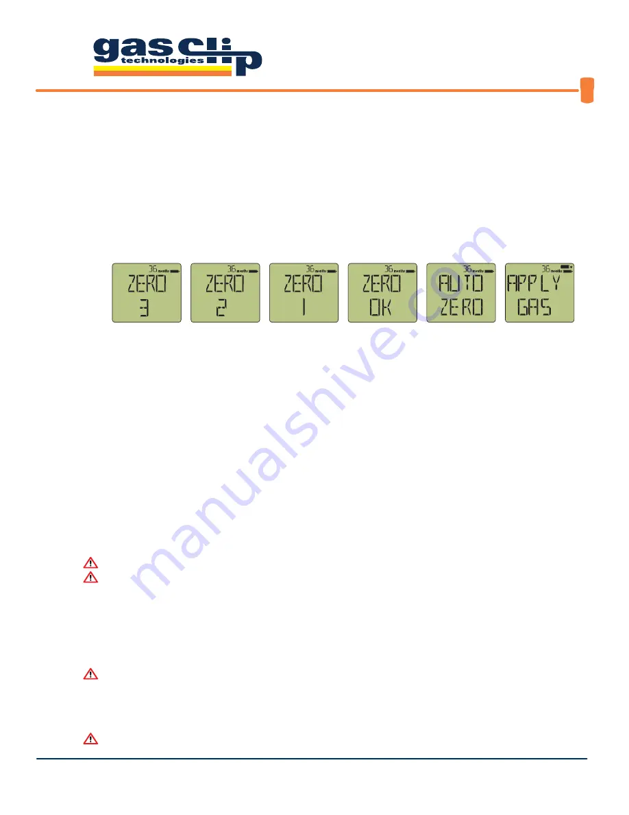
To enter the Manual Calibration mode, continuously hold down the Power/Menu Button. Release the button 

when the “ZERO OK” message appears. The detector will first automatically zero the sensors at the current 

baseline reading, then the “APPLY GAS” prompt will appear. Display will show:

Once the screen displays “APPLY GAS”, clip the MGC-S Calibration Cap (provided with the detector) into place 
over the sensor ports. Apply gas to the detector at a flow rate of 0.5 LPM and do not disturb while calibration 
is being performed. Sensor readings will be displayed as the gas is detected and as the detector adjusts the 
calibration parameters. Once calibration is complete, the detector will display the next calibration date before 
returning to normal (alarming) operation. If a sensor fails to calibrate, the detector will display “ERROR” (an 
error message for the failed sensor). Check your gas connections and concentration before attempting a 
second calibration. 

If a sensor fails to calibrate after a second attempt, contact GCT for assistance

.

Auto Zeroing

To Auto Zero the detector, enter Manual Calibration mode as described above. Once the screen displays "APPLY GAS", 
briefly press the Power/Menu Button. The screen will then display "CAL ABORT" followed by the number of days 
remaining before the next set calibration date. The detector has been successfully auto zeroed and returns to normal 
operation.


 Auto Zero the detector only in a known clean air environment .


 DO NOT Auto Zero in temperatures above or below the specified range of 0°C to 40°C .

Retest

To attempt recovery from sensor "Err", continuously hold down the Power/Menu Button during count downs.  Release 
the button when the "RETEST OK" message appears.  The detector will retest sensors and auto zero the detector.  Auto 
Zeroing precautions apply.


 Under no circumstances should a detector displaying "Err" be used .

Storage 

Store the detector in a safe, dry place between 32°F and 77°F (0°C and 25°C).


 Review the warranty period and the “Activate  before . . ." date that is printed on the product box label .

Release 

Power/Menu Button

Summary of Contents for Multi Gas Clip Simple Plus

Page 1: ...UM MGC S PLUS v1 00a Portable gas detectors you can count on 1 of 18 Multi Gas Clip Simple Plus G A S C L I P T E C H C O M User s Manual...

Page 2: ...4 Off Mode 4 Alarms 5 Alarm Behavior 5 Default Alarms 5 Detector Menus 6 Main Menu 6 Status Menu 6 Option Menu 7 Adjustable Options 7 Detector Maintenance 9 Battery 9 Bump Testing 9 Manual Bump Test...

Page 3: ...the detector to sensor poisons such as but not limited to alcohol and citrus based products Exposure to poisons may impair the accuracy and or response time of the detector If suspected sensor poisoni...

Page 4: ...Ports 4 O2 Sensor 5 Dual Tox Sensor 6 Audible Alarm Port 7 Display 8 Alarm Bar LEDs 9 Maintenance LEDs 10 Infrared IR Communication Window 11 Alligator Clip with Safety Ring 12 Certification Label 13...

Page 5: ...n Test Mode icon 3 will appear and flash indicating it is time to apply gas The Battery Indicator 4 is displayed as a battery icon which is solid as long as the battery is not low The battery won t ne...

Page 6: ...r the sensor reading while it is stabilizing and being self tested Once all sensors have completed the warm up and stabilization sequence 65 seconds the detector is fully operational and ready to dete...

Page 7: ...ry outline only 20 Minutes remaining single beep flash battery outline only 10 Minutes remaining single beep flash battery outline flashes 5 Minutes remaining continuous beep flash every 5 seconds Exp...

Page 8: ...ill immediately return to normal operation Status Menu The Status Menu is accessed by pressing the Power Menu Button once during the SHOW STATUS prompt The detector will display in the following order...

Page 9: ...is GAS CLIP TECHNOLOGIES Alarm Limits This option allows you to set sensor low and high alarm limits Each sensor contains separate alarm threshold values that tell the detector when to go into alarm...

Page 10: ...be adjusted only with the GCT IR Link by Volume CH4 Allows the detector to display gas readings as by volume CH4 rather than LEL The conversion rate can be configured by specifying what the methane co...

Page 11: ...nual Bump Test Instructions Press the Power Menu Button two separate times in quick succession double tap to access the Main Menu The display will then show in the following order When the screen disp...

Page 12: ...MGC S Calibration Cap and the detector will return to normal operation after a short period of time The bump due date will be automatically reset based on the new bump date The bump test will be recor...

Page 13: ...failed a bump test be used During a manual bump test the audible visual vibrating prompting to apply gas will continue for approximately two minutes If gas is not applied within the two minutes then...

Page 14: ...is detected and as the detector adjusts the calibration parameters Once calibration is complete the detector will display the next calibration date before returning to normal alarming operation If a...

Page 15: ...first bump test and so on Bump tests are differentiated from normal events when the alarm condition occurs inside of an MGC Simple Clip Dock or when the detector is manually bump tested according to t...

Page 16: ...ndow lined up approximately 2 3 inches apart 1 Open GCT IR Link Software downloaded for free from www gascliptech com under Resources tab 2 Click on Download Logs icon at the top left corner 3 Select...

Page 17: ...MGC S CSK Hard sided Carrying Case with Foam Insert 1 ft Sampling Probe Air Stone Particulate Filter MGC S Calibration Cap 10 ft Sampling Hose and 3 ft Calibration Test Hose with Quick Connect Hand A...

Page 18: ...ox Sensor P N MGC SE 4DT O2 Sensor P N MGC SE O2 Replacement Filters Filter Pack of 10 P N MGC S FILTER 10 Filter Pack of 2 P N MGC S FILTER 2 Various authorized replacement spare parts for Multi Gas...

Page 19: ...ge Resolution Accuracy T90 H2S 0 100 ppm 0 1 2 ppm 30s CO 0 500 ppm 1 5 ppm 30s Combustible 0 100 LEL 0 1 See Table 1 page 18 30s O2 0 30 vol 0 1 0 7 vol 15s Sensor Type H2S CO O2 Single plug in elect...

Page 20: ...s and any other applicable recommendations of GCT 2 The buyer promptly notifying GCT of any defect and if required promptly making the product available for correction No goods shall be returned to GC...

Reviews: