background image

Engine Removal and Installation

89

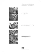
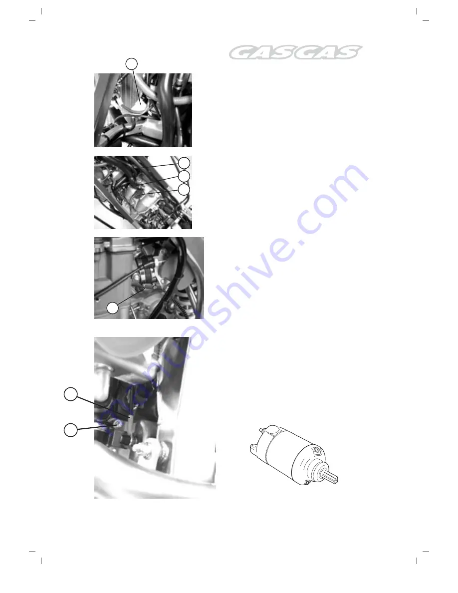
Detach the wire clamp from the alternator (A) and
the sensor cable from the tonewheel.

Detach the spark-plug arm (1), the engine-oil
devaporizing tube (2), the engine-oil reservoir
breather pipe (3).

Loosen the clamp holding the cylinder head injector
conduit (4).

Detach the wire clamp from the water-temperature
sensor (5).
Detach the connecting cable from the starter (6)
and remove the starter.

3

1

2

4

A

5

6

Summary of Contents for EC FSE 400 - SERVICE 2002 & 2003

Page 1: ...SERVICE MANUAL MOTOR FSE400 450 2002 2003 SERVICE MANUAL MOTOR FSE400 450 2002 2003...

Page 2: ...Contents Technical Specifications 84 Engine Removal and Installation 86 Engine Disassembly 96 Inspection and Maintenance of Engine Components 108 Engine Installation 136 Regular Maintenance 156...

Page 3: ...bes Aluminium Rocker Front Suspension Inverted WP 43 mm Diameter 295 mm Stroke Inverted Marzocchi 45 mm Diameter 295 mm Stroke Inverted hlins 46 mm Diameter 295 mm Stroke Rear Suspension Progressive S...

Page 4: ...Engine Removal andInstallation 86 EngineRemovalandInstallation...

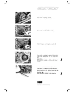
Page 5: ...a steam machine The following steps cover the disassembly sequence Remove the saddle and the frame covers Drain the oil in the engine Remove the engine plate Drain the frame oil reservoir A Drain the...

Page 6: ...eel Detach the spark plug arm 1 the engine oil devaporizing tube 2 the engine oil reservoir breather pipe 3 Loosen the clamp holding the cylinder head injector conduit 4 Detach the wire clamp from the...

Page 7: ...EngineRemovalandInstallation 90 Remove the water tubes 1 Remove the lever from the pedal operated starter Remove the exhaust manifold 2 Detach the radiator tubes 1 2...

Page 8: ...ovalandInstallation 91 Detach the engine oil tube 1 in the frame reservoir Remove the gearbox lever Remove the engine pinion cover Remove the clutch pump Loosen the chain Remove the outlet pinion Seeg...

Page 9: ...EngineRemovalandInstallation 92 Remove the engine pinion Remove the split pin and the brake pedal CAUTION Replace the split pins with new ones Remove the engine from the frame...

Page 10: ...are self locking Upon removal they cease to be self locking and become useless CAUTION Replace the nuts securing the engine with new ones Secure the screwheads with a spanner and tighten the nuts sec...

Page 11: ...of this pinion must be duly noted so that the same wear CW ACW direction may be preserved Attach the engine pinion Seeger Attach the tube to the frame reservoir Tighten the exhaust manifold screw 1 a...

Page 12: ...W 40 viscosity oil into the oil inlet located in the frame 1 and check the level DETAILS Engine oil capacity Oil replacement 1 7 l Oil and filter replacement 1 9 l Overall engine check 1 9 l Start the...

Page 13: ...EngineDisassembly EngineDisassembly 96...

Page 14: ...nder head lid must be removed with the piston in the compression stroke PMS Remove the cap bolt 1 and the timing chain idler 2 Remove the spark plug 5 Then remove the cylinder head lid screws in a dia...

Page 15: ...er head side screw Remove all four cylinder head screws in a diagonal sequence NOTE Prior to loosening the cylinder head screws loosen the cylinder head screws 6 mm and the cylinder base screws Remove...

Page 16: ...In case of difficulty removing the cylinder tap it with a plastic mallet Remove the cylinder gasket 5 and the centering devices 6 Cover the cylinder base with a clean cloth to prevent the piston bolt...
Page 17: ...tach the oil filter lid 1 and the oil filter 2 Remove the starter followers 3 the centering devices 4 and the gasket 5 Remove the pressure pump lid 1 and the rotor 2 101 EngineDisassembly 3 4 5 1 2 1...

Page 18: ...g devices 3 and the gasket 4 Loosen the clutch spring screws in a diagonal sequence as illustrated and remove them when they become totally loose Detach the clutch press and the disc assembly Remove t...

Page 19: ...b and the washer CAUTION The clutch hub has a specific fitting position in respect of the input shaft Mark the position with an indelible marker on the lubrication groove This mark must be taken into...

Page 20: ...iate gear 4 Detach the foot operated starter assembly Detach the pedal operated starting pawl plate 6 Detach the pedal operated starter intermediate pinion shaft Detach the oil pump intermediate gear...

Page 21: ...e crankshaft pinion bolt the washer the gear the timing chain and the timing chain gear CAUTION The crankshaft pinion bolt has a left hand thread Remove the alternator rotor bolt and washer Holding th...

Page 22: ...it Remove the lower oil reservoir lid Remove the crankcase left hand set screws Detach the crankcase using the special tool supplied Tool Part No ME2595000 crankcase detachment tool NOTE Fit the cran...

Page 23: ...arbox input shaft assembly 3 and the gearbox output shaft assembly 4 Detach the crankshaft 5 and the rocker shaft 6 NOTE Should this detachment operation prove difficult tap both shafts with a plastic...

Page 24: ...der head 110 Camshaft Automatic decompression assembly 120 Piston and piston ring 122 Connecting rod 125 Crankshaft 126 Starter clutch 126 Oil pump 127 Clutch 127 Shifter forks and gear 128 Transmissi...

Page 25: ...part Set them in groups exhaust admission so that they may be assembled in their original positions CYLINDERHEAD Disassembly Detach the intake pipe Detach the engine coolant pipe bracket Remove the t...

Page 26: ...springs and then use the special tools provided to remove the valve rod semicones Tool Part Description valve spring compressor Tool Part Description Adapter Tool Part Description Pliers Remove the va...

Page 27: ...ylinder head gasket for signs of deformation Measure the clearance in several places If any of the clearance measurements is found to exceed the service limit replace the cylinder head with a new one...

Page 28: ...of wear are found replace the valve involved with a new one Measure the thickness T of the valve working surface If the thickness is found to exceed the specified value replace the valve with a new on...

Page 29: ...art Description Valve guide puller fitter NOTE Discard the valve guide Only oversize valve guides are available as spares Use the valve guide reamer and shank to smooth the valve guide holes in the cy...

Page 30: ...ed value DETAILS Valve seat width W Normal 0 9 1 1 mm 0 035 0 043 in Grind the valve seat as required if it is found to exceed the specified value Valve seat maintenance Inlet and exhaust valve seats...

Page 31: ...itial seat cutting operation Use the 45 knife to descale and clean the seat Turn the knife around once or twice Measure the valve seat width W after each cutting operation If the valve seat appears to...

Page 32: ...ion and width use the 60 knife very slightly to remove any burrs resulting from the previous cutting operations CAUTION Do not use any burnishing compounds after completing the final cutting operation...

Page 33: ...valve seat pressed A weak spring will result in loss of engine power and valve mechanism clattering Check the strength of the valve springs by measuring their unsupported length and the amount of str...

Page 34: ...the valves into their guides Fit the valve spring with the lesser pitch end facing the cylinder head A Lesser pitch B Greater pitch C Down Fit the spring clip by pressing it with the tappet Fit the se...

Page 35: ...ly If the automatic decompressor counterweight does not work smoothly replace it with a new one Cam wear Cam wear usually results in the loss of the valve settings and in a subsequent loss of power Us...

Page 36: ...idge oil clearance is found to exceed the service limit measure the bridge bracket inside diameter and the bridge outside diameter Change either the camshaft or the cylinder head and the camshaft brac...

Page 37: ...2 in Inner cylinder wall Check the inner cylinder wall for scratches notches or any other signs of damage Measure the cylinder inside diameter at six points Tool Description cylinder gauge set DETAILS...

Page 38: ...E450 1 1 23 mm 2 1 53 mm Lubrication 2 01 2 03 mm Tool Description Micrometer 0 25 mm DETAILS Piston ring thickness Fig 3 Normal FSE400 1 0 985 mm 2 1 19 mm FSE450 1 1 19 mm 2 1 49 mm Piston ring free...

Page 39: ...one Tool Description Dial gauge 1 1000 mm Tool Description small calibre gauge 18 35 mm DETAILS Piston bolt inside diameter Service limit 20 030 mm Use the micrometer to measure the piston bolt outsid...

Page 40: ...t play This method is also useful in checking the amount of wear shown by the component parts of the connecting rod crank end Tool Description magnetic support Tool Description dial gauge 1 100 mm Too...

Page 41: ...ocks 100 mm DETAILS Crankshaft offsetting Service limit 0 08 mm ST ARTERCLUTCH Remove the hexagonal screws 1 Starter clutch screw 26 Nm 2 6 Kgf m Fit the starter clutch in the correct direction as ill...

Page 42: ...limit 2 62 mm DETAILS Driving disc hook width Normal 13 9 mm Service limit 13 5 mm Clutch driven discs Using the feeler gauge measure the amount of deformation shown by the clutch driven discs If any...

Page 43: ...gearbox Use the feeler gauge to measure the clearance of each fork in the groove of its gear If the clearance is found to exceed the specified value replace the fork its gear or both Tool Description...

Page 44: ...ion to the location and position of washers and spring rings The sectional view shows the correct positions for gears washers and spring rings When fitting a spring ring attention must be paid to its...

Page 45: ...ut shaft 1 using the special tool provided Tool Description bearing pulling device set CAUTION Replace the removed bearing with a new one Fit the RH bearings on the gearbox input shaft using the speci...

Page 46: ...ing set Crankshaft bearings Remove the RH 5 and LH 6 bearings from the crankshaft using the special tool provided Tool Description bearing pulling device set CAUTION Replace the removed bearings with...

Page 47: ...rocker shaft 9 using the special tool provided Tool Description bearing pulling device set CAUTION Replace the removed bearing with a new one Fit the RH bearing on the rocker shaft Tool Description be...

Page 48: ...ntion to the following points CAUTION Replace the removed seals with new ones Apply grease on the seal lips Gearbox output shaft seal Remove the bushing 1 Remove the seal from the gearbox output shaft...

Page 49: ...e Remove the lid 1 the ball in the oil check valve 2 and the RH crankcase spring 3 Attach the spring 3 the oil check valve ball 2 and the lid 1 to the RH crankcase Cleaning the oil filter and the cran...

Page 50: ...Input drive gear 142 Oil pump 142 Starting pawl 143 Camshaft timing chain 143 Clutch 144 Crankcase RH cover 146 Clutch cover 146 Alternator rotor cover 146 Piston ring 147 Piston and cylinder 148 Cyl...

Page 51: ...ed to pull from its LH end towards the crankcase Tool Description crankshaft fitter Tool Description adaptor CAUTION Do not attach the crankshaft to the crankcase by tapping it into position with a pl...

Page 52: ...fork shaft 5 No 3 shifter fork 6 Desmodromic device Fit the shifter forks into the shifting grooves in their correct positions and directions Fit the shafts of the shifter forks NOTE After fitting the...

Page 53: ...rank end and to the transmission gears Should the engine feature an oil sump gasket replace the gasket Otherwise with no sump gasket apply silicone on the right sump contact surfaces and to the A part...

Page 54: ...tor nut 100 Nm 10 Kgf m ROCKERSHAFT 1 Rocker or vibration absorbant shaft 2 Bearing 3 Rocker shaft driven gear 4 Washer 5 Water pump retainer 6 Water pump turbine 7 Washer A Rocker shaft nut When fitt...

Page 55: ...que Input drive gear nut 110 Nm 11 Kgf m OILPUMP Before fitting the oil pump apply motor oil to the sliding surfaces of the pump housing the outer rotor the inner rotor and the shaft When fitting the...

Page 56: ...ner 13 Starter inner pinion 14 Washer 15 Shaft Seeger Fit the pedal operated starter shaft assembly and attach the spring end to the crankshaft protuberance CAMSHAFTTIMINGCHAIN Attach the camshaft tim...

Page 57: ...12 Clutch hub 13 Clutch seal washer 14 Clutch hub lock nut 15 Clutch rod 16 A Driving disc 7 items 16 B Driving disc 1 item 17 driven disc 7 items 18 Clutch mushroom 19 Exhaust valve needle cage 20 Ne...

Page 58: ...he specified torque Tool Description Clutch hub holder Clutch hub nut 70 Nm 7 Kgf m Bend the washer tongue firmly Fit the clutch driving discs and driven discs into the clutch hub one by one and in th...

Page 59: ...VER Tighten the screws on the clutch disc cover firmly NOTE Fit the new seal and the screws A on the clutch disc cover as illustrated AL TERNA TOR ROTORCOVER Fit the starter driven gears 2 the centeri...

Page 60: ...ring groove and then fit both side guides 2 The spacer and the side guides have no specific top and bottom They may be fitted in any position CAUTION When fitting the spacer prevent its two ends from...

Page 61: ...ing surface of the piston and the connecting rod crank end Attach the centering pins 1 and a new seal 2 to the crankcase CAUTION Use a new seal to prevent oil leaks Hold the piston rings with their se...

Page 62: ...que Cylinder head screw Initial 25 N 2 5 kgf m Final 46 N 4 6 kgf m NOTE Apply motor oil to the threaded areas of the cylinder head screws and their washers Position the washers with their rounded fac...

Page 63: ...ly and slightly pull the chain upwards to remove any clearance between the camshaft chain driving pinion and the exhaust camshaft pinion The exhaust camshaft pinion bears an arrow marked 1 1 Turn the...

Page 64: ...s top cup should be checked If the clearance does not correspond to the one expressed in DATA the valve shim must be changed by another one that corresponds to the adequate setting CYLINDER HEADCOVER...

Page 65: ...chain idler CAUTION Use a new seal to prevent oil leaks Attach the camshaft driving chain idler to the cylinder and then tighten both Allen screws at the specified torque Camshaft chain tension adjust...

Page 66: ...RegularMaintenance RegularMaintenance 154 Spark Plug 156 Engine Oil and Oil Filter 157 Engine oil pipework 159...

Page 67: ...ound to be out of tolerance adjust the tolerance DETAILS Standard Tolerance 0 7 0 8 Tool Thickness gauge Electrode Check the condition of the electrode If the electrode is found to be extremely worn o...

Page 68: ...engine When the oil has been drained insert and tighten the screws at the specified torque and pour a new supply of oil through the filling hole Every time the oil is renewed without replacing the fi...

Page 69: ...ind the filter has been positioned correctly Replace the oil filter lid and tighten the lock nut Replace the supply of new oil in the engine and check the oil level as described for the oil replacemen...

Page 70: ...ed at the specified torque and that the valves have been properly adjusted Warm up the engine before commencing the compression check Make sure that the battery is fully charged Carry out the compress...

Page 71: ...cuit Warm up the engine as follows Summer 10 minutes at 2000 rpm Winter 20 minutes at 2000 rpm After warming up the engine incrase the turning speed to 3000 rpm check the tachometer and record the oil...

Page 72: ...Notes Notas Notes 191...

Page 73: ...Notas Notes 192...

Page 74: ...Torremirona 17190 Salt Girona SPAIN Tel 34 902 47 62 54 Fax 34 902 47 61 60 E mail officegg gasgasmotos es partsgg gasgasmotos es Web www gasgasmotos es Ref PU010238031 2 edici n revisada FEBRERO 2003...

Reviews: