GC-IMS
– User Manual
40/214
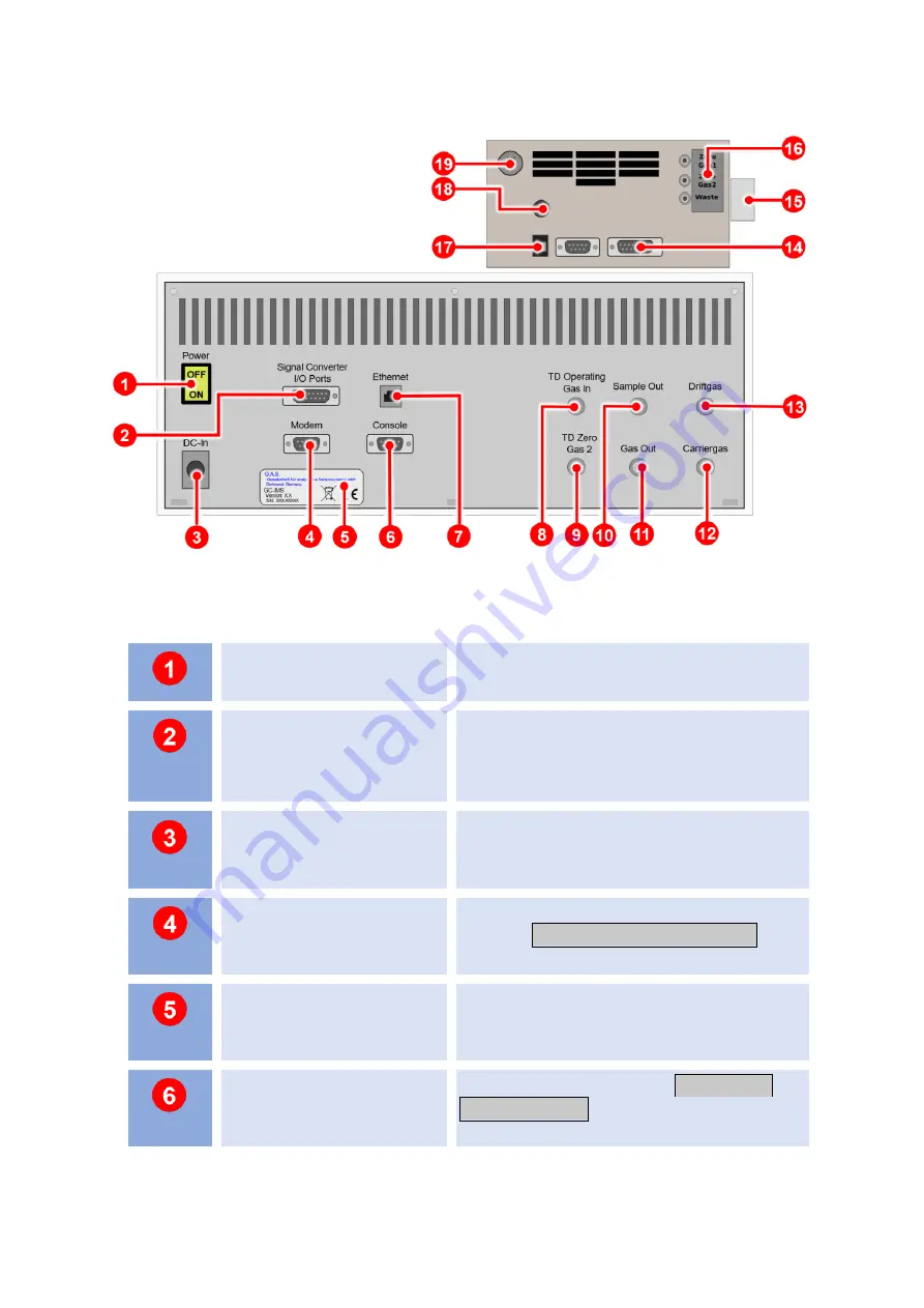
5.4.3.3 Rear
Figure 14: GC-IMS with Airsence µTD - Housing of device - Rear
Power Switch
Switches the device on or off.
Signal Converter
–I/O
Socket
Socket for connecting a PLC
(Programmable Logic Controller) or other
devices.
DC-In Socket
24V XLR-Connector for connecting the
power supply.
Modem Socket
Socket for connecting an external
modem.
For service purposes only
.
Device Type/Serial
Number Plate
Displays manufacturer identification,
device type, serial number and version.
Console Socket
Console interface socket.
For service
purposes only.
Summary of Contents for GC-IMS
Page 1: ...User Manual GC IMS G A S Gesellschaft f r analytische Sensorsysteme mbH...
Page 150: ...GC IMS User Manual 150 214 4 Device without top cover...
Page 164: ...GC IMS User Manual 164 214 17 Tighten the three screws of the frontplate...
Page 188: ...GC IMS User Manual 188 214 9 4 Technical drawing Internal Gasflow...
Page 212: ...GC IMS User Manual 212 214 Tutorials VOCal Manuals VOCal...


