background image

-24- 


Figure 7, Tank overview 1


Summary of Contents for Super

Page 1: ...HAMBURGER FORMING MACHINE Mod SUPER...

Page 2: ...NING 12 9 TROUBLESHOOTING 16 10 GENERAL DIAGRAM 17 10 1 Overview 17 10 2 Chassis overview 19 10 3 Former shaft overview 21 10 3 1 Overview complete former bearing housing 22 10 4 Tank overview 23 10 4...

Page 3: ...es around the world and not just in the hamburger sector We are aware that our work would be of no value without the trust of our existing clients and partners or the interest shown by those who wish...

Page 4: ...13849 1 2008 AC 2009 and is in conformity with the following directives Machinery directive 2006 42 CE Low voltage directive 2014 35 UE Electromagnetic compatibility directive 2014 30 UE It is forbidd...

Page 5: ...types of steel and plastic from which the machine is constructed and which are in contact with the meat comply with the hygiene rules and regulations in force Plastic material polyethylene terephthal...

Page 6: ...ability for improper use of the machine The machine has been designed for use with food products and must be used in the way described in this manual Any use other than the specified one will involve...

Page 7: ...placing paper on one side 7 Produces round patties of 30 to 120 mm diameter and other shapes these must be concentric with a circle and of the measurements mentioned above 8 Weight controllable with a...

Page 8: ...e advise you notify the distributor or INDUSTRIAS GASER S L directly 6 2 Start up 1 These machines essentially consist of 3 parts chassis former unit and tank Image 1 Main parts 2 It is important that...

Page 9: ...It is vital that when you perform the calibration of the thickness of the patties the calibration gear makes full turns so that the mark on the gear lines up with the arrow on the protection Image 3...

Page 10: ...an be adjusted using the weight calibration gear Turn it a few degrees to the left or right until the mark on the gear lines up with the grooves on the protection Image 5 calibration 1 Image 6 calibra...

Page 11: ...er of disassembly Remember that when you change the shape the weight might vary 6 3 2 Paper dispenser To place paper on the patties fit the paper dispenser Pos 5 overview First insert the shaft Next i...

Page 12: ...keeping it as horizontal as possible when lifting it Image 9 Removing paper positioner 2 Next remove the tank Pos 8 tank overview To do this lift the cover of the tank Pos 15 tank overview extract th...

Page 13: ...view loosening the safety screw Pos 9 tank overview by turning it clockwise Image 14 Removing safety screw Image 15 Removing vanes 4 Next disassemble the base of the tank Pos 3 tank overview The two k...

Page 14: ...shaft overview Image 16 Removing former shaft nut Image 17 Removing former unit 6 Clean the disassembled components with pressurised water and dry well using compressed air if possible Clean the mach...

Page 15: ...y check the condition of the extractor slice thread Pos 12 overview If it is necessary to change the thread to remove it bend the slice then you can easily remove the thread and replace it with a new...

Page 16: ...ll does not start Safety sensors have come lose Calibrate security sensors Electrical connections or components in poor condition See manual 8 Maintenance point 4 The patties do not come out well form...

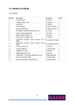
Page 17: ...ANISM UNIT S1150000 1 8 MAIN PROTECTION UNIT S1160000 1 9 ELECTRICAL CABINET UNIT S1250000 1 10 STAINLESS CHEESE HEAD SCREW M6 16 DIN84 FE0108M060160084 2 11 STAINLESS CHEESE HEAD SCREW M6 20 DIN84 FE...

Page 18: ...18 Figure 1 Standard overview 1 Figure 2 Standard overview 2...

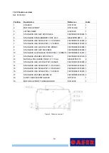
Page 19: ...M060000985 1 9 STAINLESS HEX NUT M6 DIN934 FE0108M060000934 1 10 STAINLESS ALLEN GRUB SCREW M6 16 DIN913 FE0108M060160913 1 11 STAINLESS WASHER M10 DIN125 FE0108M100000125 5 12 NATURAL POLYAMIDE TUBE...

Page 20: ...20 Figure 4 Chassis overview 2...

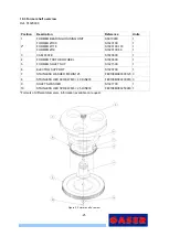
Page 21: ...3 CAM PLATE S1020600 1 4 FORMER TOOTHED WHEEL S1020300 1 5 FORMER SHAFT NUT S1021500 1 6 EJECTOR SUPPORT S1020700 1 7 STAINLESS WASHER M8 DIN125 FE0108M080000125 3 8 STAINLESS HEX SCREW M8 40 DIN933...

Page 22: ...020500 1 4 RETAINING SEAL SI0209R254707 1 5 E 52 DIN472 STAINLESS CIRCLIP SI0109I520472 1 6 BEARING SI0109CI255215 2 7 FORMER BOX SEPERATOR S1021400 1 8 AXIAL BEARING SI0509115 1 9 FORMER LOWER BEARIN...

Page 23: ...001587 3 18 O RING VITON FPM 70 SHA 32 2 mm SI060903202 2 19 STAINLESS ALLEN GRUB SCREW M8 10 DIN 913 FE0108M080100913 3 20 FLAT HEAD STAINLESS ALLEN SCREW M6 20 DIN7991 FE0108M060207991 5 21 STAINLES...

Page 24: ...24 Figure 7 Tank overview 1...

Page 25: ...25 Figure 8 Tank overview 2...

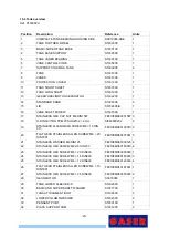
Page 26: ...OUSING TANK S1035400 1 2 TANK BOX SEPARATOR S1037000 1 3 TANK UNIT SHAFT S1035200 1 4 BEARING SI0109CI255215 2 5 AXIAL BEARING 25 42 11 FE SI0509115 1 6 RETAINER SI0209R255207 1 7 STAINLESS CIRCLIP E...

Page 27: ...27 10 4 2 Gear motor Ref SS970000 Position Description Reference Units 1 MOTOR EL1420BG075B14 1 2 GEAR SI0525BR0319120 1 Figure 10 Gear motor overview...

Page 28: ...sition Description Reference Units 1 EXTRACTOR S1040200 98 S1040200 118 S1040200 50 1 1 1 2 INNER FORMER HEAD S1040300 1 3 EJECTOR S1040400 1 4 COMPRESSION SPRING S1040500 1 5 I 35 DIN 472 STAINLESS C...

Page 29: ...200 S1080200 118 1 3 DISPENSER ROLLER S1080400 1 4 ROLLER SHAFT S1080600 1 5 DISPENSER WEIGHT PLATE 100 DISPENSER WEIGHT PLATE 118 S1080500 S1080500 118 1 6 BUSHING ID8 ED10 H10 SI04090010008010 2 7 S...

Page 30: ...00 2 7 CALIBRATION WHEEL PROTECTION S1160600 1 8 WHEEL STOP S1023000 1 9 FLAT HEAD STAINLESS ALLEN SCREW M6 16 DIN7991 FE0108M060167991 3 10 STAINLESS WASHER M6 DIN125 FE0108M060000125 4 11 STAINLESS...

Page 31: ...N471 SI0109E150471 1 4 STAINLESS WASHER M4 DIN125 FE0108M040000125 4 5 STAINLESS HEX LOCK NUT M4 DIN985 FE0108M040000985 4 6 STAINLESS ALLEN SCREW M4 35 DIN912 FE0108M040350912 4 7 STAINLESS HEX SCREW...

Page 32: ...PROTECTION S1160200 1 3 REAR PROTECTION S1161300 1 4 DISPENSER GUIDE SLEEVE S1080700 1 5 MECHANISM PROTECTION KNOB S1010300 1 6 STAINLESS HEX LOCK NUT M6 DIN985 FE0108M060000985 1 7 STAINLESS HEX NUT...

Page 33: ...EEN PILOT LED EL2120PRVD22220 1 6 M20 1 5 METAL GLAND EL0208RPM20 3 7 M20x1 5 METAL GLAND NUT EL0208TPM20 3 8 ORANGE 8 POLE FEMALE CONNECTOR EL0220C08PH 1 9 SINGLE PHASE PLUG EL0220CEM 1 10 FREE HANGI...

Page 34: ...34 12 WIRING DIAGRAMS...

Page 35: ...ER VER 01 Final de proyecto Lugar de instalaci n N mero de p ginas E mail 24 V Fax Empresa 230 VAC 380 VAC Tel fono 2018 Obra Fax Tensi n de mando F26_Gaser Modificado Descripci n de proyecto Responsa...

Page 36: ...Potenciometro 10K control de velocidad FC1 Final de carrrera seguridad tapa cerrada FC2 Final de carrrera seguridad plato formador H1 Se alizaci n marcha Verde H2 Se alitzaci n paro Rojo Cuadro El ctr...

Reviews: