background image

1. INDUSTRIAS GASER

Since   its   foundation   in   1969,   INDUSTRIAS   GASER   has   specialised   in   manufacturing   a   range   of

stainless-steel machinery for the meat industry.

Since   1985   we   have   constantly   developed   technology   for   GASER-brand   hamburger-forming

machines, developing a distinctive system based on a SIMPLER, MORE EFFECTIVE AND MORE

ECONOMICAL TECHNIQUE.

In the 1990s, INDUSTRIAS GASER expanded into markets in various countries around the world, and

not just in the hamburger sector.

We are aware that our work would be of no value without the trust of our existing clients and partners

or the interest shown by those who wish to join them.

We thank them all.

            INDUSTRIAS GASER

       GASER EUROPA


Salt, Girona, SPAIN

         L’viv, UKRAINE

INDUSTRIAS GASER Ctra, Bescanó, 15, Pol. Torre Mirona 17190 Salt (Girona) - Spain 

Tel. 34 972 23 65 72 | Fax 34 972 23 63 66 | Whatsapp: (34) 679 49 65 06

email: 

gaser@gaser.com

GASER EUROPA вул.Б.Лепкого,1 81160 смт.Щирець Пустомитівский р-н Львівська область

Украіна - Ukraine 

Tel. 38 (03230) 67251/84 

Fax 38 (03230) 67191

email: 

gasereuropa@gaser.com

For more information about the company and its products:


www.gaser.com

-3-

Summary of Contents for T-70

Page 1: ...SEMIAUTOMATIC TYING MACHINE Mod T 70...

Page 2: ...2 Start up 8 7 CLEANING 12 8 MAINTENANCE 13 9 TROUBLESHOOTING 14 10 GENERAL DIAGRAM 15 10 1 Overview 15 10 2 Tying machine gears overview 19 10 3 Tying machine gears with tying tube 20 10 4 Tensioner...

Page 3: ...around the world and not just in the hamburger sector We are aware that our work would be of no value without the trust of our existing clients and partners or the interest shown by those who wish to...

Page 4: ...49 1 2008 AC 2009 UNE EN ISO 4414 2011 and is in conformity with the following directives Machinery directive 2006 42 CE It is forbidden to make any change or modification to the machine without the p...

Page 5: ...pes of steel and plastic from which the machine is constructed and which are in contact with the meat comply with the hygiene rules and regulations in force Plastic material polyethylene terephthalate...

Page 6: ...lity for improper use of the machine The machine has been designed for use with food products and must be used in the way described in this manual Any use other than the specified one will involve ris...

Page 7: ...y 80 litres minute 6 Knee operated control with attachment for automatic tying 7 54 mm inlet 8 Adjustable choking 9 Speed adjustable from 50 to 140 operations minute 10 Tying with three turns of the t...

Page 8: ...he machine is completely clean to ensure it works properly 2 It must be connected to a compressed air network Its normal operating pressure is 4 to 6 kg cm2 depending on how quickly you want it to ope...

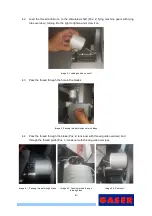
Page 9: ...obbin on shaft 4 3 Pass the thread through the hole in the blades Image 3 Passing thread through hole in blades 4 4 Pass the thread through the brake Pos 2 tensioner with thread guide overview and thr...

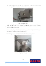
Page 10: ...t of the machine there is an air flow control By turning it you can adjust the air flow and consequently the speed of work 6 When adjusting the speed of operation do not set it to the minimum speed as...

Page 11: ...ou want to work continuously insert the lever fixing shaft Pos 32 overview Image 7 Inserting lever fixing shaft 9 During operation it is necessary to ensure that the bobbin does not come off its suppo...

Page 12: ...iew Image 8 Opening the lid 2 Remove thread bobbin If this is not removed when cleaning this can encourage the growth of bacteria owing to the damp Image 9 Removing thread bobbins 3 The machine is rea...

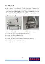
Page 13: ...at the bottom and the lubrication point at the top When the machine is new we recommend lubricating it every 8 hours of work or when it will be stopped for more than 2 days Image 10 Side lubrication...

Page 14: ...2 Start up point 6 Pneumatic fault See manual 8 Maintenance point 4 The machine does not operate at the desired speed Insufficient inlet air pressure See manual 6 2 Start up point 2 Poorly adjusted a...

Page 15: ...00 1 14 UPPER VANE SHAFT 00020500 1 15 CRANK AXLE 00020600 1 16 CHOKE BLADES LOWER GUIDE 00020700 2 17 TYING UNIT CRANK 00022400 1 18 CHOKE BLADES 00022500 2 19 TYING DEVICE CHOKING ROD 00022600 2 20...

Page 16: ...1 42 NOT VALVE NE0215NOTC 1 43 NOT VALVE BASE 1 8 NE03157097K18 1 44 MANIFOLD NE0315DJ5214 2 45 E 28310 LIMIT SWITCH NE0315E28310 1 46 T 70 DRIVE GEARS LIMIT SWITCH NE0315ER18310 2 47 DISTRIBUTOR 40...

Page 17: ...Figure 2 General overview 2 Figure 3 General overview 3 17...

Page 18: ...Figure 4 Pneumatic elements 18...

Page 19: ...HREAD BOBBIN SUPPORT CONE 00070500 1 3 THREAD TENSIONER INERTIA BRAKE BASE 70071100 1 4 THREAD TENSIONER INERTIA BRAKE SUPPORT 70071200 1 5 THREAD TENSIONER INERTIA BRAKE COUNTERWEIGHT 70071300 1 6 TH...

Page 20: ...000 Number Description Reference Units 1 TYING MACHINE GEARS OVERVIEW 77620000 1 2 TYING CORE 00070200 1 3 TYING TUBE 00070300 1 4 TYING LUBRICATION POINT SI0122EHCM8 1 5 PLAIN BEARING SI0409070065050...

Page 21: ...erview Ref 77610000 Number Description Reference Units 1 THREAD TENSIONER SUPPORT 00070600 1 2 THREAD TENSIONER 00070700 1 3 T 72 TYING MACHINE THREAD TENSIONING SPRING SI011418102096 1 Figure 7 Tensi...

Page 22: ...e gear overview Ref 77630000 N Position Description Reference Units 1 TYING MACHINE DRIVE GEARS 00090100 1 2 DRIVE GEAR CAM 00091200 2 3 T 72 METAL DRIVE GEAR SPACER 70090200 1 Figure 8 Drive gear ove...

Page 23: ...on Reference Units 1 T 72 DRIVE GEAR SHAFT 70090500 1 2 T 72 DRIVE GEAR SHAFT WASHER 70090700 1 3 T 72 LARGE INTERIOR RING REINFORCEMENT 70091400 1 4 T 72 LARGE INNER RING 70091500 1 5 TYING LUBRICATI...

Page 24: ...Description Reference Units 1 INTERMEDIATE GEARS SHAFT 70091700 1 2 T 72 SMALL INNER RING 70091600 1 3 T 72 SMALL RING REINFORCEMENT 70091800 1 4 TEFLON WASHER 70091900 1 5 TYING LUBRICATION POINT SI...

Page 25: ...r regulator with pressure gauge unit Ref 77550000 Number Description Reference Units 1 FILTER REGULATOR 1 4 NE0215FR08B14 1 2 PRESSURE GAUGE NE0215M12B40 1 Figure 11 Filter regulator with pressure gau...

Page 26: ...FOLD NE0315DJ5214 2 5 E 28310 LIMIT SWITCH NE0315E28310 1 6 T 70 DRIVE GEARS LIMIT SWITCH NE0315ER18310 2 7 DISTRIBUTOR 40 40 20 1 4 NE0315R4040201 1 8 INTERNAL DISCHARGE VALVE NE0315VDI14 1 9 TYING M...

Page 27: ...Pneumatic diagram 1 27...

Page 28: ...28...

Reviews: