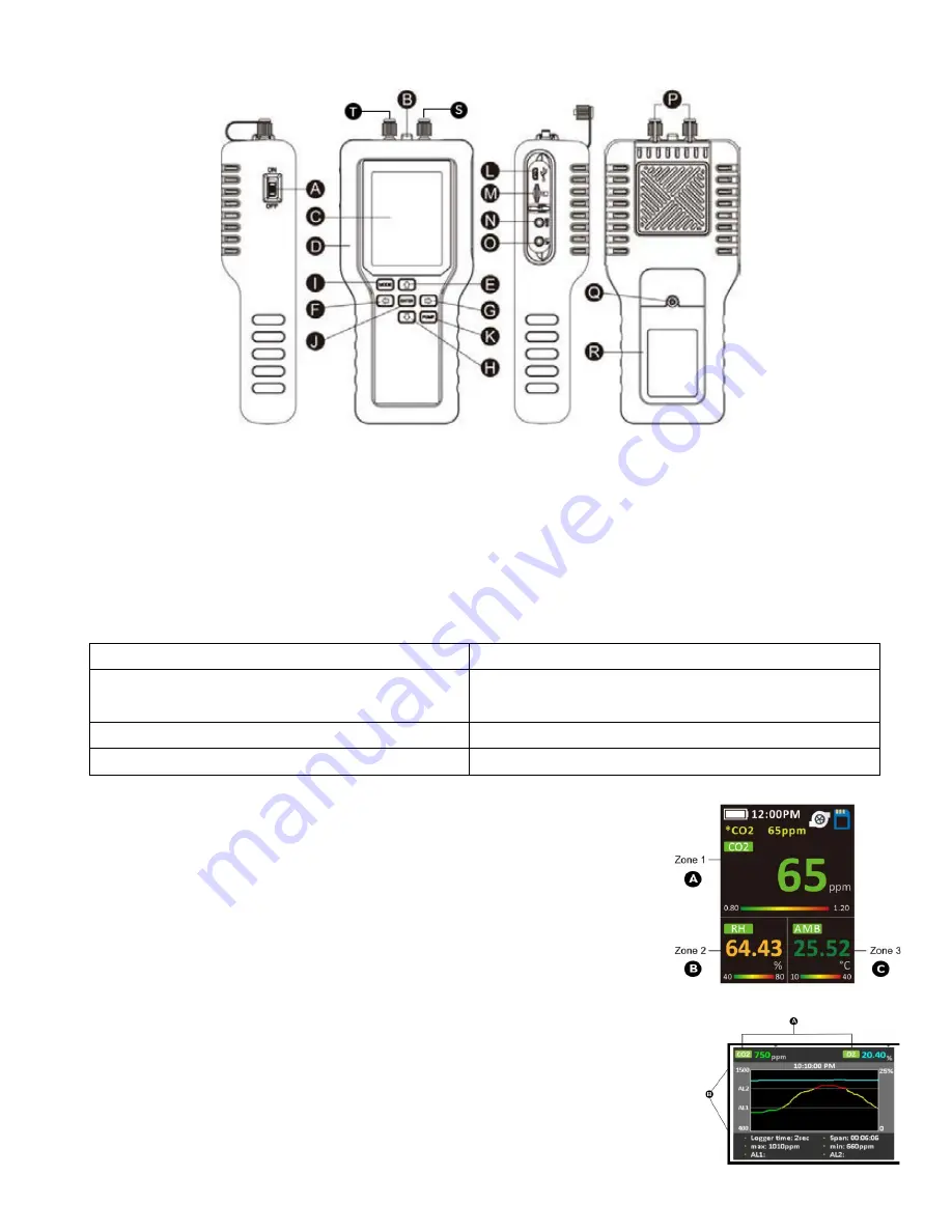
INSTRUMENT OVERVIEW
A.
Power Switch On/Off
B.
Temp/Humidity Sensor
C.
LCD Displays Screen
D.
Rubber Enclosure
E.
Up Key
Button description:
F.
Left Arrow Button
G.
Right Arrow Button
H.
Down Arrow Button
I.
Mode Button
J.
Enter Button
K.
Pump Button
L.
USB Socket
M.
SD Card Slot
N.
Programming Port
(INTERNAL use only)
O.
4-20mA Connection
MODE (
○
I
)
Enter the setting menu.
Up (
○
E
) / Down (
○
H
) / Left (
○
F
) / Right (
○
G
)
Change parameter values or select options.
Enter (
○
J
)
Execute a command
PUMP (
○
K
)
Start the pump or data logger
(
Does not turn pump off, must wait for sample period
)
LCD Display
The Full Color Liquid Crystal Display (LCD) shows the following features:
•
CO2 concentration level in parts‐per‐million (ppm or %)
•
O2/CO/CH4 concentration levels in percentage format (##. ##%)
•
RH, AMB, DP. and ALTI
•
Time, Battery Life (upper left)
•
SD Card Logging Icon ON/OFF (upper right)
•
Sampling Pump Active/Inactive (upper right)
•
Percentage of batteries
1.1 Main LCD Display Screen
1.2 Built-In Data Log Screen
1.1
Main LCD Display
A.
Zone 1 - Gas Concentration Display
B.
Zone 2 - Gas Concentration or RH/T
C.
Zone 3
–
TEMP / BARO / DP
A.
Gas Concentration Levels (ppm or %)
B.
Y Axis - PPM and Alarm Levels
C.
X Axis - Logger Time / Span
1.2
Built‐In Data Log Screen
P. Luer Caps
Q. Battery Cover Screw
R. Battery Cover
S. Inlet Cap
T. Outlet Cap
6


