(Part No. 233885)
Installation Instructions
Read and follow these instructions (in conjunction with the Jewel / Spectre
Freestanding manual) carefully before installing this appliance.
SAVE THESE INSTRUCTIONS
Sheet
1
of
6
GPN
234969
F:\Docs\Manuals\Heaters\Heaters\GPN 234969 Jewel Spectre Thru Wall
Minimum
requirements
This Heater has been tested to AS2918:2001 Appendix B.
Test Report No. ASFT18004 - 1
kit.
For the through wall installation additional
8˝ stainless is to be
over the 7˝ stainless active
then a 9˝ mesh
shield and a 10˝ stainless steel
shield are to be installed, both to ceiling height.
(See diagram opposite)
9˝ solid back
mesh
8˝ stainless
7˝ stainless
!
10˝ stainless steel
shield up to
drop box height
NB: First
height 4600 mm (+/– 300mm) from
protector
In
te
rn
al
w
al
l
120mm
min.
These must be used to make the installation conform.
Jewel / Spectre Through Wall Kit
• The installation of this appliance must be carried out as per the manual and the flue manufactuer’s specifications
We recommend that you use a qualified installer to carry out the installation.
• Default clearance values and flue requirements specified in AS/NZS 2918-2001 must be used for any clearance values not
given in these instructions.
• If in doubt, do not hesitate to contact your local Jindara or Eureka dealer.
• This appliance weighs in excess of 230 kilograms. Extreme care should be taken when handling the appliance.
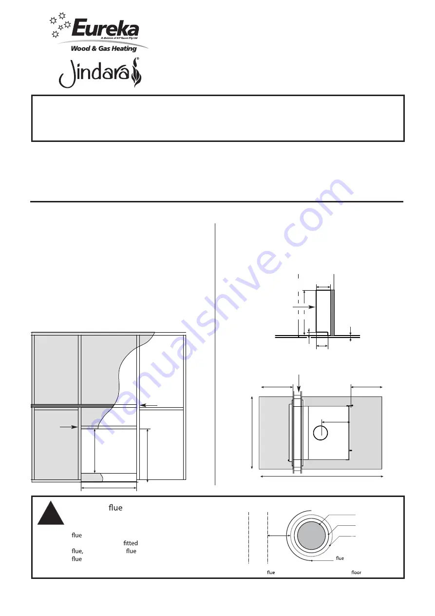
• This thru-wall kit is designed for use with plasterboard stud walls,
with a total thickness ranging between 90mm and 110mm.
• Note that the wall section below the appliance fascia on the insert
side is filled, as per figure 1. It should be supported by a stud with a
10mm x 35mm horizontal cut-out, as per figure 2. This is to allow
the base of the freestanding unit to protrude far enough through
the wall.
Hole cutting dimensions & clearances to combustibles
0$7(5,$/0DWHULDOQRWVSHFLILHG!
),1,6+
'5$:1
7,7/(
$33'
-,*
6+((7
2)
5(9 %< (&11R '$7(
5(9 %< (&11R '$7(
5(/($6('
'21276&$/(
$
6&$/(
3$571R
7+,6,1)250$7,21,6&21),'(17,$/$1'5(0$,167+(
3523(57<2)$)*$62137</7'81'(5&23<5,*+7/$:
$)*$62137</7',1&,19,&725,$
5(*,67(5('2)),&(
%/$.(675((7$5$5$7
9,&725,$
0$66NJ
7+,5'
$1*/(
352-(&7,21
67$1'$5'0(75,&72/(5$1&(681/(6663(&,),('27+(5:,6(
',0(16,2166+2:17+86RU
'5,//('+2/(6381&+('+2/(6$1*/(6
)25/$6(5&87&20321(176
)256+((7PP$1'81'(572/(5$1&(
)256+((7WRPP72/(5$1&(
)256+((7WRPP72/(5$1&(
Figure 1
See
Notes 1 & 2
See
Note 3
890 mm
860 mm
714mm
Note 1: If present, a combustible mantle shelf must be positioned
a minimum of 500mm above the apliance hot air outlet.
Note 2: Combustible internal wall framing must not be installed
less than 475mm above the appliance top plate.
Note 3: Non-combustible internal wall framing must be used if
installed directly above the appliance, less than 475mm
from the top plate.
0$7(5,$/0DWHULDOQRWVSHFLILHG!
),1,6+
'5$:1
7,7/(
$33'
-,*
6+((7
2)
5(9 %< (&11R '$7(
5(9 %< (&11R '$7(
5(/($6('
'21276&$/(
$
6&$/(
3$571R
7+,6,1)250$7,21,6&21),'(17,$/$1'5(0$,167+(
3523(57<2)$)*$62137</7'81'(5&23<5,*+7/$:
$)*$62137</7',1&,19,&725,$
5(*,67(5('2)),&(
%/$.(675((7$5$5$7
9,&725,$
0$66NJ
7+,5'
$1*/(
352-(&7,21
67$1'$5'0(75,&72/(5$1&(681/(6663(&,),('27+(5:,6(
',0(16,2166+2:17+86RU
'5,//('+2/(6381&+('+2/(6$1*/(6
)25/$6(5&87&20321(176
)256+((7PP$1'81'(572/(5$1&(
)256+((7WRPP72/(5$1&(
)256+((7WRPP72/(5$1&(
Insert
side
35 mm
15 mm
Floor protection
minimum thickness
6 mm
45 mm
110 mm
Freestanding
side
Horizontal lower
support stud
• A minimum 1590mm x 940mm floor protector with a minimum
thickness of 6mm must be installed under the appliance, as per
figure 3.
• The floor protector must extend a minimum of 420mm from each
appliance door and 155mm from the pedestal base on either side
of the appliance.
Figure 2
0$7(5,$/0DWHULDOQRWVSHFLILHG!
),1,6+
'5$:1
7,7/(
$33'
-,*
6+((7
2)
5(9
%<
(&11R
'$7(
5(9
%<
(&11R
'$7(
5(/($6('
'21276&$/(
$
6&$/(
3$571R
7+,6,1)250$7,21,6&21),'(17,$/$1'5(0$,167+(
3523(57<2)$)*$62137</7'81'(5&23<5,*+7/$:
$)*$62137</7',1&,19,&725,$
5(*,67(5('2)),&(
%/$.(675((7$5$5$7
9,&725,$
0$66NJ
7+,5'
$1*/(
352-(&7,21
67$1'$5'0(75,&72/(5$1&(681/(6663(&,),('27+(5:,6(
',0(16,2166+2:17+86RU
'5,//('+2/(6381&+('+2/(6$1*/(6
)25/$6(5&87&20321(176
)256+((7PP$1'81'(572/(5$1&(
)256+((7WRPP72/(5$1&(
)256+((7WRPP72/(5$1&(
Internal wall
Figure 3
420mm
420mm
940mm
1590mm
372mm
using an Australian Standard


