Ground Drive
– Monitor Operation
Page
32
05/06
Introduction (Ground Drive)
All Gason Ground Drive air seeders
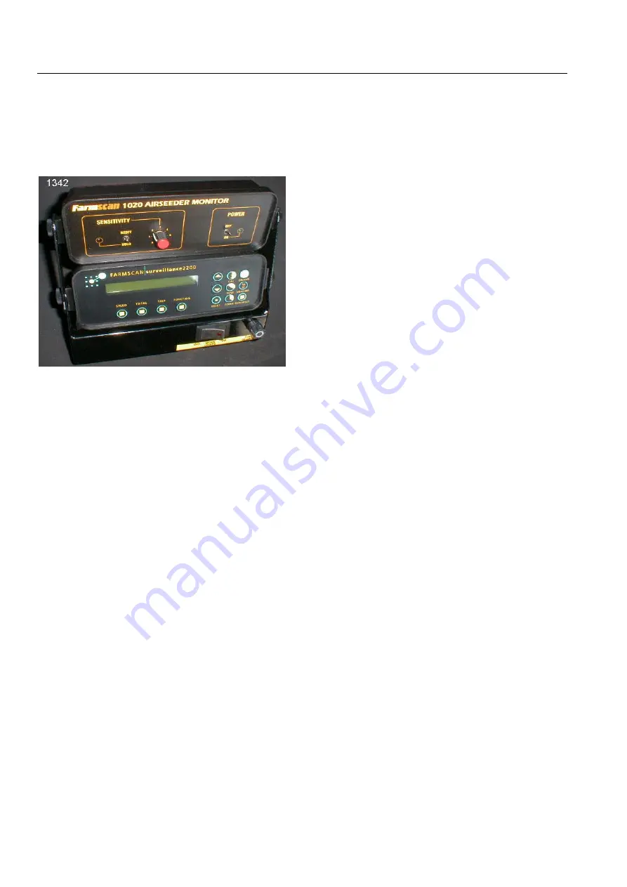
are equipped with the Farmscan 2200
Surveillance monitor.
Fig.G1 Ground Drive Seeder Monitors and
worklight switch bracket.
The 2200 Surveillance monitor has
been configured and loaded with the preset
alarm values. The monitor will however
require operator input for the calibration
width of the cultivator being used.
Setting Implement Width
The calibration width is the actual
sowing width in metres. To load this value
simply:
Press the
‘CAL’
key to display
‘WIDTH’
.
Press the up or down arrow keys to set
the appropriate sowing width in metres.
Once set press either the speed, area or
function keys to close the calibration
program.
Monitor Operation
The
monitor
is
linked
to
an
independent clutch switch that engages the
metering system and places the monitor
either on or off hold.
If the monitor is switched on but the
clutch is off, the monitor will repeat the
message
‘MONITOR ON HOLD’
. This is
simply alerting the operator that the clutch
is disengaged and that the trip meter has
stopped measuring distance/area covered
and that alarms are de-activated.
When the clutch switch is turned on
the message
‘MONITOR OFF HOLD’
will
appear once to tell the operator that normal
seeding operations have commenced. The
monitor will now operate the trip meters as
well as any alarms that have been set.
The
Alarms
have been given preset
values as standard at the factory (refer
page 29). All alarms can be reset at any
time or removed altogether if desired.
Refer to the monitor’s handbook for a full
explanation of the alarms and their control.
The
speed, total area
and
trip area
keys have multiple functions and are fully
explained in the monitor’s handbook.
The
function
key on your Gason Air
Seeder has been specifically set-up to
monitor 6 different areas of operation on the
seeder.
1. FAN
Displays the speed of the
blower impeller in rpm.
2. SHAFT 1
Shows the speed of the
first metershaft in rpm.
3. SHAFT 2
Shows the speed of the
second metershaft in rpm.
4. SHAFT 3
Shows the speed of the
third metershaft if fitted.
5. PRESSURE Displays the air pressure
in the plenum chamber in
kPa.
6. BIN LEVEL
Displays the current bin
status . Bin OK will show
if product is above all
sensors. Bin Low when
below at least one sensor.
The different functions are operated by
continually pressing the function key. This
will allow the operator to go from fan speed
to the shaft speeds etc and back again to
the fan speed.


