VRT Hydraulic Drive
– Monitor Operation
Page 67
05/06
Message Display
If during the process of seeding a
problem occurs with the seeder’s operation
an alarm will be displayed in the lower right
hand corner of the screen.
For a full explanation of all possible
alarms refer to the Message Display section
in the Farmscan Operator’s Manual. The
most common alarms are listed in the
following table.
UNIT ON HOLD
Monitor not in use.
FAN STOPPED
Fan stopped. Metering system
will not run.
FAN SLOW
Fan below low alarm point.
Metering system will not run.
FAN FAST
Fan above high alarm point.
Fan speed must not exceed
4500rpm.
BIN 1 LOW
Bin level below sensor height
on bin no.1. No alarm on bin 4
DRIVE 1-3 FAST
Variation of Sprocket Ratio.
Check the preset value on the
alarms ratio page.
DRIVE 1-3 SLOW
Variation of Sprocket Ratio.
Check the preset value on the
alarms ratio page.
BIN 1-4 RATE HI
Over target rate
BIN 1-4 RATE LO
Under target rate
NO COMMS
Pod not responding.
Table.V8 Common Alarms.
Refer to the VRT Trouble Shooting section
in this manual for further explanation (p93).
SAFETY (VRT)
The VRT seeder uses hydraulic
motors to turn the metering system. The
hydraulic motors, which are mounted on the
left hand side of each meterbox, takes
hydraulic flow from the tractor to rotate.
The motors can be operated from
the tractor or the seeder. Hydraulic flow is
supplied to the metering system whenever
the tractor’s hydraulics have been engaged
to run the fan or auger, if fitted.
It is important to disengage the tractor’s
hydraulic system and to
TURN THE
TRACTOR OFF
before attempting to work
on or around the metering system. The
metering system could be activated if
someone pushes the prime key or calibration
function from the monitor.
The hydraulic motors can also be
started from the seeder via the red/green
calibration buttons on the left hand side of
the seeder or the front face of the pod.
Movement can also occur by rotating one or
all of the large thumb knobs located on the
front face of each bank of the manifold.
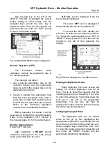
Fig.V9 Manual override valve.
Protective hinged guards have been
fitted to the side of each meterbox with
warning decals. Ensure that the guards
remain in place and that the decals are
readable.
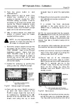
Fig.V10 Safety guard and decal.


