VRT Hydraulic Drive
– Maintenance
Page 92
05/06
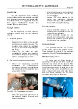
If the light does not flash at every
tooth you may need to reduce the sensor’s
clearance to the target, or check that the
target runs true. Loosen the lock nuts on
the sensor with a spanner and move it
closer to the target checking that there is
sufficient clearance to prevent damage from
occurring. Do not over tighten the lock nuts
after adjustment. Sensors are generally set
with a 2 to 4mm clearance.
Meter Drive
Proximity Sensor
There are 2 ways to check the performance
of the proximity sensors mounted next to
the meter drive motors.
1. Check the drive ratio alarms screen on
the monitor in the cab while seeding.
2. Manually
operating
each
hydraulic
motor to check that the light on the end
of the sensor indicates consistently.
Monitor Checking Procedure
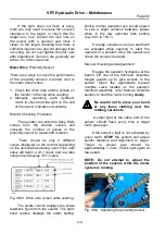
The operator can enter the Drive Ratio
screen from the Alarms screen and
compare the number of pulses of the
proximity sensor to metershaft rotations.
There should be only 2 different
values displayed on the monitor depending
on the sprocket ratio being used. High ratio
setup will return a 24:1 count, and low ratio
setup should display 105:1 value.
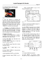
Fig. VM3 Drive ratio screen while seeding.
The centre column displays the actual
feedback figure from the seeder. The right-
hand column displays the alarm setting.
During normal operation you would expect
to see a slight variation between pulses
when in the low sprocket ratio setting
(eg.104:1 to 105:1).
If a large variation occurs an alarm will
be activated while seeding to alert the
operator of a problem. Stop the seeder and
check the sensors manually.
Manual Checking and Adjustment
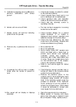
Engage the seeder’s hydraulics at the
tractor. Lift one of the left-hand meterbox
hinged guards up to give access to the
sensor. Open the appropriate manual
override valve located on the s
eeder’s
manifold assembly, refer Manual Override
section, to start the motor turning
slowly
.
Be careful not to place your hand
or any loose clothing near the
rotating sprockets.
A small light at the cable end of the
sensor should flash every time a target
tooth goes past.
If the sensor’s light is not activated by
every tooth,
STOP
the system and adjust
sensor distance and alignment to target.
Target
to
sensor
gap
should
be
approximately 1-3mm. Check light again at
low speed.
NOTE: Do not attempt to adjust the
position of the sensors while the meter
system is running.
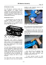
Fig. VM4 Adjusting the proximity sensor.


