USE AND MAINTENANCE
ENGLISH
62
-
cod. G19502891
4.4 PREPARATIONS FOR SOWING
To obtain the most correct investment of the seeds per hectare (kg/
Ha) the distribution parts must be adjusted properly: the gear-box,
the feelers, rollers and sliding doors. Use the sowing table to nd
the relevant instructions (refer to the sowing test chapter 4.10.5).
To proceed, the values to follow are: the type of seed (wheat,
barley, etc.), the amount in kg to be distributed per hectare and
the distance between the rows to be sowed.
4.4.1 SPEED CHANGE GEAR
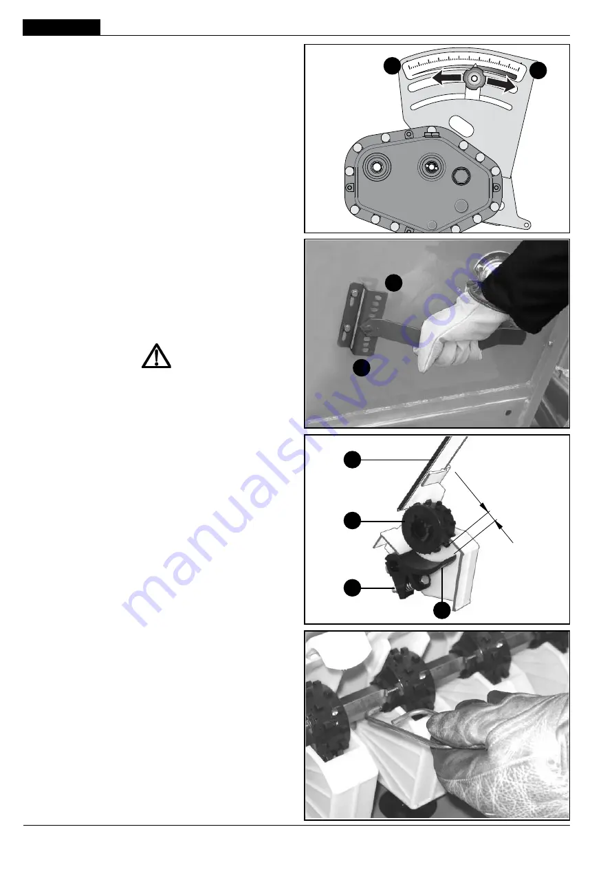
The gear shift is located on the right side of the seeder and receives
motion from the drive wheel. The gear shift is used to change speed
to the seed distribution units through the adjustment lever which is
calibrated on a continuous scale of
1
to
55
(Fig. 21).
Loosen the knob, move the lever to bottom of scale «0» (zero) and
then set it to the value indicated. Lock it by tightening the knob.
4.4.2 FEELER ADJUSTMENT
The feeler adjustment lever (Fig. 22) is positioned on the left side
of the machine and works according to a graduated scale that runs
from 0 - 9 settings. The lever must be set to the number indicated
by the sowing table on the basis of the type of seed to be sown.
If the feelers (
I
, Fig. 23) are correctly positioned, they assure a uid
and constant distribution of the seeds.
ATTENTION
The lever positioned beyond the maximum opening, causes
the discharge of the seeds from the hopper.
For best seeding results, periodically check the position of the fee-
ler pins (
I
): the lever (Fig. 22) in
position “0”
, adjust the distance
between the feeler and the distributor roller (
H
) by means of the
nut (
M
) to 0,5 ÷ 1 mm (Fig. 23).
4.4.3 DISTRIBOTOR ROLLER ADJUSTMENT
The most appropriate type of seed distributor roller must be selected
prior to sowing on the basis of the type of seed being drilled (
H
,
Fig. 23). The machine is tted with rollers for small, medium and
large seeds. Select the type of distributing roller according to the
information given in
Table 6
(page 70). Which is selected by in-
serting the key supplied (Fig. 24) into the slot on the left side of the
roller and push the drag retainer all the way out. Perform the a.m.
operation in inverse order to retum the roller to its initial position.
g. 22
g. 24
g. 23
0,5÷1 mm
9
0
L
H
M
I
g. 21
55
1
Summary of Contents for DAMA
Page 4: ...4 cod G19502891 ...
Page 42: ...42 cod G19502891 Notes ...
Page 80: ...Notes ...
Page 118: ...118 cod G19502891 Notes ...
Page 156: ...156 cod G19502891 ...
Page 171: ... 171 À G19502891 ºÃ 11 ºÃ 10 ºÃ ÃĺÄÎ µ ÂºÄ Í Ä ºÈÍ Áº  º ÑÃÎ Å º  º ÀÂÀ ÀµÀ º ºÑ ª ª ºÃ ...


