USE AND MAINTENANCE
ENGLISH
g
47
cod. G19502491
3.12 TRAILED VERSION
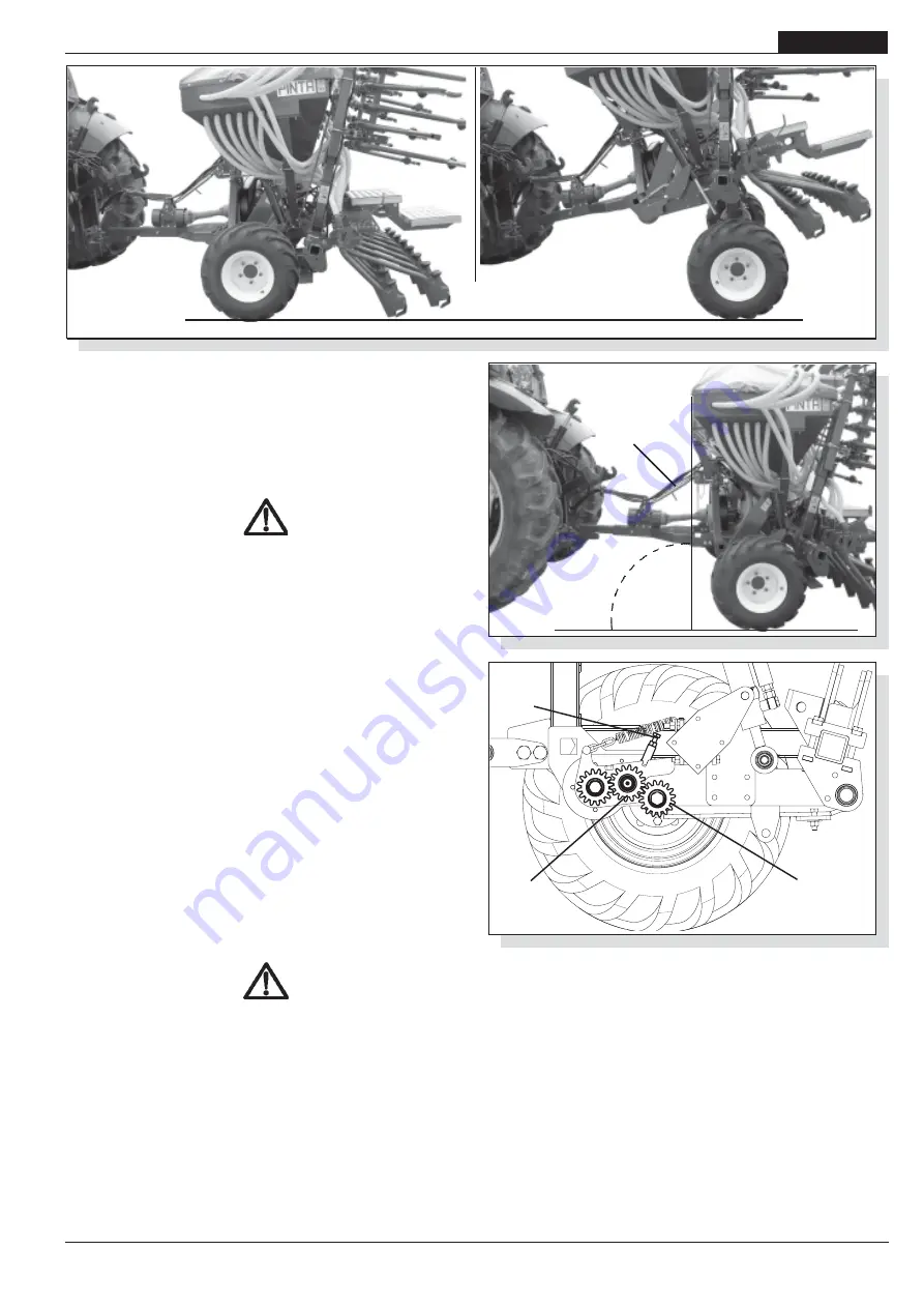
On request, the mounted version of the seed drill can be
equipped with a transforming element to make it trailable (Fig.
38). Applicable to tracked tractors, the trailed seed drill is ideal for
planting in hilly areas.
3.12.1 ATTACHMENT TO THE TRACTOR
DANGER
The attachment to the tractor is a very dangerous phase. Be
very careful in following the instructions for the whole operation.
HOOKING
The correct positioning of the tractor/seeder is determined by
placing the unit on a horizontal surface.
1) Attach the equipment to the tractor's load hooking bolt. Secure
the load hooking bolt by means of the safety pin; using the
regulating tie-rod (C Fig. 39) ensure that the seed drill is
perpendicular to the ground (Fig. 39).
2) Connect the Cardan shaft and make sure that it is perfectly
blocked on the power take-off Check that the protection turns
freely and fix it with the special chain.
3) The hydraulic pipes must be connected correctly to the tractor
distributors (see chapter 3.1) following the instructions on
each pipe.
4) Check the length of the grain tubes (with the machine
completely hoisted) to avoid bendings and consequently
breaking of the tube, as well as the formation of loops (Fig.
10).
During the work, regularly check that the equipment is
perpendicular.
UNHOOKING
DANGER
Unhooking the seed drill from the tractor is a very dangerous
operation. Great caution must be used and the whole operation
must be carried out following the instructions.
For a correct unhooking operation of the seed drill it is necessary
to proceed on a horizontal level.
1) Lower the supporting base elements
2) Slowly lower the
seed drill until it rests completely on the
ground.
3) Disconnect the hydraulic pipes from the tractor distributors
and protect the quick couplings with the caps.
4)
Unhook the Cardan shaft from
the tractor and put it on the
special hook.
5)
Detach the equipment from the tractor's load hooking bolt.
TRANSMISSION
The movement is transmitted from the wheel to the dosing device
by meshing the gears (D-E, Fig. 40).
Check that the gears are correctly meshed at the beginning of
the season (presence of "play" between D-E).
If the gears are meshed tightly, adjust the regulating screw (F,
Fig. 40).
Failure to mesh the gears properly could lead to the breaking
of the gear's support shaft (D).
The transmission disengages automatically when the equipment
is lifted to the transporting position (B, Fig. 38).
fig. 40
fig. 38
fig. 39
90°
C
D
E
(A)
(B)
F
Summary of Contents for PINTA
Page 4: ...g 4 cod G19502491...
Page 27: ...g 27 cod G19502491 Notes...
Page 28: ...g 28 cod G19502491...
Page 51: ...g 51 cod G19502491 Notes...
Page 52: ...g 52 cod G19502491...
Page 75: ...g 75 cod G19502491 Notes Notes Notes Notes Notes...
Page 76: ...g 76 cod G19502491...
Page 99: ...g 99 cod G19502491 Notes...
Page 100: ...g 100 cod G19502491...
Page 123: ...g 123 cod G19502491 Notes...
Page 124: ...g 124 cod G19502491...


