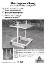
d
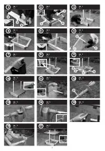
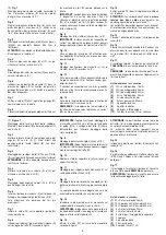
Abb. 1
Montage der Sandkastenwände. Montieren Sie je
2 Stk. Seitenbretter (B) mit Eck-Füßen (C) mit
Schraube (1).
Abb. 2
Einsetzen der Seitenbretter (A) und Verschrau-
bung an den Eck-Füßen (C) mit Schraube (1).
Achten Sie auf die Positionierung der Seitenbretter
(B) mit Loch! (Gegenüberliegend!)
Abb. 3
Montage der Dachsteher (D) mit Schrauben (5)(8)
(9). Die Dachsteher werden außenseitig montiert!
HINWEIS: Die Hutmuttern sollen jeweils nach
außen zeigen!
Abb. 4
Auflegen der Sitzbretter (E) und (F), ausrichten und
mit Schrauben (2) befestigen!
Abb. 5
Montage der farbigen Ecken (Q) an allen vier
Ecken mit Schrauben (3).
Abb. 6
Einstecken des Sicherungsbolzens (P) in das Gie-
belbrett (G) sowie Befestigen des Führungsschuhs
(M) mit Schrauben (4). Achten Sie auf die vorge-
stanzten Lochpositionen!
Abb. 7
Einfädeln des Seils (10) in den Führungsschuh (M)
lt. Abbildung.
Abb. 8
Einsetzen der vormontierten Giebelelemente (G) in
die Dachsteher (D) lt. Abbildung.
WICHTIG: Schneiden Sie aus dem Verpackungs-
karton vier Kartonstreifen mit je ca. 10x5 cm aus
und stecken Sie diese zwischen Führungsschuh
(M) und Dachsteher (D) als Abstandhalter für die
weitere Montage der Firstlatten (H).
Abb. 9
Montage der Firstlatten (H) mit Schrauben (2).
WICHTIG: Anschließend Kartonstreifen entfernen!
Die Giebelelemente müssen sich in den Dach-
stehern (D) leicht bewegen können!
Abb. 10
Aufsetzen der Dachfolie (U) und Befestigung mit
Dachpappnägel (6).
Abb. 11
Montage der Kurbelhalterung (L) auf Dachsteher
(D) mit Schraube (3).
Abb. 12
Aufstecken der Kurbel (N) beidseitig auf die Alumi-
niumachse (K) und Fixierung mit Splint (7).
Die Splinte sind sorgfältig umzubiegen und ggf.
mit etwas Klebeband abzukleben!
Abb. 13
Einsetzen der vormontierten Kurbelachse in die
Kurbelhalterung (L) und Verschraubung mit
Schraube (2).
HINWEIS: Die Leichtgängigkeit der Kurbel und
die Bremsfunktion wird durch leichteres oder stär-
keres Festziehen dieser Schrauben erreicht!
Abb. 14
Einfädeln des Seils (10) in die Kurbelachse lt. Ab-
bildung!
ACHTUNG: Die Seile müssen beidseitig gleich
stark gespannt sein, um ein paralleles Hochfahren
des Daches zu garantieren!
Überstehende Seilenden sollten ggf. gekürzt und
mit Klebeband an der Aluminium-Achse abgeklebt
werden.
Abb. 15
Einsetzen der Augenschutzplatte auf den Siche-
rungsbolzen (P).
Abb. 16
Zum Heben und Senken des Daches ist mit der
zweiten Hand am Dachsteher (D) entgegenzuhal-
ten. Das verringert die Hebelwirkung!
Abb. 17
Fertiger Aufbau! Der Sicherungsbolzen ist im ge-
öffneten Zustand
IMMER einzurasten.
HINWEIS: Der Sicherungsbolzen kann durch
leichtes Anheben des Daches gelöst werden!
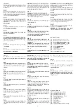
Stückliste Zubehör:
(1) 32 Stk. Rundkopfschrauben 16 mm
(2) 28 Stk. Spanplattenschrauben 40 mm
(3) 18 Stk. Spanplattenschrauben 20 mm
(4) 8 Stk. Rundkopfschrauben 20 mm
(5) 4 Stk. Schlossschrauben 55 mm
(6) 8 Stk. Dachpappnägel
(7) 2 Stk. Splinte
(8) 4 Stk. Beilagscheiben klein
(9) 4 Stk. Hutmuttern
(10) 2 Stk. Seil, je ca. 117 cm
g
Fig. 1
Assemble the sandbox walls. Attach the 2 side
boards (B) to the corner bases (C) using screws
(1).
Fig. 2
Insert side board (A) and attach to corner base (C)
with screw (1). Make sure you position side board
(B) so that it lines up with the hole! (on the opposi-
te side!)
Fig. 3
Mount the cover supports (D) with screws (5)(8)(9).
Mount the cover supports on the outside!
NOTE: The cover nuts should each face the out-
side!
Fig. 4
Put on seat boards (E) and (F) and align and attach
with screws (2)!
Fig. 5
Install the colored corners (Q) in all four corners
with screws (3).
Fig. 6
Insert the safety pin (P) into the cover support
board (G) and attach the guide shoe (M) with
screws (4). Use the punched holes!
Fig. 7
Thread cable (10) into the guide shoe (M) as per
the illustration.
Fig. 8
Insert the preassembled cover support boards (G)
into the upright cover supports (D) as per the illus-
tration.
IMPORTANT: Cut four 10 x 5 cm cardboard strips
from the packaging box and put them between the
guide shoes (M) and cover supports (D) as spacers
for further assembly of the crossbars (H).
Fig. 9
Install each of the crossbars (H) with screws (2).
IMPORTANT: Remove cardboard strips! The
cover support bars must be able to move easily in
the cover supports (D)!
Fig. 10
Put the cover foil (U) into place and use roofing felt
nails (6) to attach.
Fig. 11
Install the crank bracket (L) on to the cover sup-
port (D) with screw (3).
Fig. 12
Attach the cranks (N) on both sides to the alu-
minium axle rod (K) and fix with cotter pins (7).
Carefully bend the cotter pins and adhere with
some adhesive tape if necessary!
Fig. 13
Insert the preassembled crank axle rod into the
crank bracket (L) and fasten them with a screw (2).
NOTE: Smooth movement of the crank and bra-
king function are achieved by lightly or strongly ti-
ghtening this screw!
Fig. 14
Thread the cable (10) into the crank axle rod as per
the illustration!
ATTENTION: The cables must be tightened the
same on both sides to ensure parallel raising of
the cover!
Trim off the ends of the excess rope, if necessary,
and seal them with tape at the aluminum spindle!
Fig. 15
Put the eye protection plate on the safety pins (P).
Fig. 16
Use your free hand to hold the cover support (D)
when raising and lowering the cover. This reduces
the leverage effect!
Fig. 17
Assembled play set! The safety pins must
ALWAYS be locked in place when the cover is up.
NOTE: The safety pins can be detached by lightly
lifting the cover!
Accessory parts list
(1) 32 round-head screws 16 mm
(2) 28 chipboard screws 40 mm
(3) 18 chipboard screws 20 mm
(4) 8 round-head screws 20 mm
(5) 4 carriage bolts 55 mm
(6) 8 roofing felt nails
(7) 2 cotter pins
(8) 8 small washers
(9) 8 cover nuts
(10) 2 pieces of cable, each 117 cm long
5

