4.3
ADJUSTMENT OF THE GAS RATE
All the instructions written below are for the exclusive
use of qualified service technicians or installers. All the
boilers are supplied already calibrated and tested.
Ad ustments are only be made with special tools.
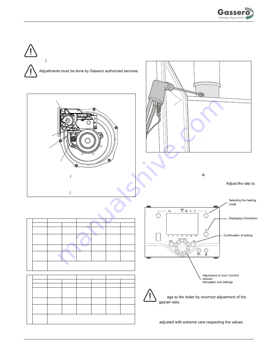
4.3.1 Description of the adjustment points
A - Maximum output ad ustment screw
B - Outlet pressure tap
C - Inlet pressure tap
D - Minimum output ad ustment screw
4.3.2 Combustion values adjustment table
4.3.3
Maximum output adjustment
1 - Connect the gas analyser probe to the sampling test point
on the flue adapter.
2
WARNING:
Dam
To ensure correct operation the values have to be
indicated in the table.
- For operating in the max. output, press at least 3 seconds to
heating mode when the boiler in mode.Controller function stop
will appear on the screen.Than press information button, it will
indicate the modulation rate (%) on the screen.
100% for max. output setting with using of navigation button. Then
press OK . Thus, boiler will operate in maximum power.
Instructions for the installer
16
100 %
B
D
A
C
Model
Q
min.
max.
min.
max.
min.
max.
CO
2
%
8,9
9,2
8,9
9,2
8,9
9,2
Gas Flow
Rate
(m
3
/h)
0,9
4,2
0,9
5,1
1,57
6,7
Fan Speed
(rpm)
1250
5100
1250
6000
1700
6500
Flue Gas
Mass
(g/sec.)
3,7
17,7
3,7
21,6
6,9
28,4
Nozzle
Diameter
(mm)
Model
Q
min.
max.
min.
max.
min.
max.
CO
2
%
8,9
9,4
8,9
9,4
8,9
9,2
Gas Flow
Rate
(m
3
/h)
1,0
4,80
1,0
5,9
1,82
7,8
Fan Speed
(rpm)
1300
5100
1300
6250
1700
6500
Flue Gas
Mass
(g/sec.)
3,7
17,4
3,7
21,3
7
28,4
Nozzle
Diameter
(mm)
Wallcon 42
Wallcon 50
Wallcon 67
G20
7,7
G25
Wallcon 42
Wallcon 50
Wallcon 67
9,5


