© 2021, Gast Manufacturing
We reserve the right to make any alterations which may be due to any technical improvements
Printed in the USA
4
Part No. 70-7100 (Rev. A)
MOUNTING
This product can be installed on a horizontal surface . Mounting
the product to a stable, rigid operating surface and using
supplied shock mounts will reduce noise and vibration . This
product is provided with vibration mounts and adjustable
mounting foot . To adjust mounting pattern, loosen vibration
mounts to and slide mounting bracket to desired location . Secure
vibration mounts to body and mounting bracket before attaching
compressor to application .
Optional mounting orientation is available. Consult Factory or
Distributor for details.
PLUMBING
Remove plugs from the IN and OUT ports . Connect with pipe
and fittings that are the same size or larger than the product’s
threaded ports . Be sure to connect the intake and exhaust
plumbing to the correct inlet and outlet ports . Ports will not
support plumbing .
ACCESSORIES
The product’s external intake and exhaust muffler will provide
adequate filtration in most applications . Check filters periodically
and replace when necessary . Consult your Gast Distributor/
Representative for additional filter recommendations .
Install relief valves and gauges at inlet or outlet or both, to
monitor performance . Check valves may be required to prevent
back streaming through the pump .
MOTOR CONTROL
It is your responsibility to contact a qualified electrician
and assure that the electrical installation is adequate and in
conformance with all national and local codes and ordinances.
The metal capacitor must be grounded.
Determine the correct overload setting required to protect the
motor (see motor starter manufacturer’s recommendations) .
Select fuses, motor protective switches or thermal protective
switches to provide protection . Fuses act as short circuit
protection for the motor, not as protection against overload .
Incoming line fuses must be able to withstand the motor’s
starting current . Motor starters with thermal magnetic overload
or circuit breakers protect motor from overload or reduced
voltage conditions .
The wiring diagram supplied with the product provides required
electrical information . Check that power source is correct to
properly operate the dual-voltage motors .
WARNING
Electrical Shock Hazard
This product must be properly grounded.
Do not modify the plug provided. If it will not fit the outlet,
have the proper outlet installed by a qualified electrician.
If repair or replacement of the cord or plug is necessary,
do not connect the grounding wire to either flat blade
terminal. The wire with insulation that is green or
green with yellow stripes is the grounding wire.
Check the condition of the power supply wiring.
Do not permanently connect this product to wiring that
is not in good condition or is inadequate for the
requirements of this product.
Failure to follow these instructions can result in death, fire,
or electrical shock.
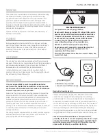
grounding pin
220/240-volt grounded
connectors will differ in shape.
Model with a Power Supply Cord
This product must be grounded . For 220/240-volt circuits
connect power supply cord grounding plug to a matching
grounded outlet . Do not use an adapter . (See above diagram .)
In the event of an electrical short circuit, grounding reduces the
risk of electric shock by providing an escape wire for the electric
current . This product may be equipped with a power supply cord
having a grounding wire with an appropriate grounding plug .
The plug must be plugged into an outlet that is properly installed
and grounded in accordance with all local codes and ordinances
Check with a qualified electrician or serviceman if the
grounding instructions are not completely understood, or if you
are not sure whether the product is properly grounded. Do not
modify the plug provided. If it will not fit the outlet, have the
proper outlet installed by a qualified electrician.


