10
| en
HOT START
it is used especially in the area of medium and lower currents for improved bur-
ning of the welding arc. the optimal setting is 30 – 35 %. in case of burn-through
in thin materials welding it is necessary to lower the function’s value or to shut
the function off.
ARC FORCE
this function helps to stabilize the arc and maintain an optimal distance of the
welding arc. it also helps to limit arc extinction and sticking of the electrode. the
optimal setting is approximately 25 – 40 %. We chose thinner electrodes for low
values and stronger electrodes for higher values.
Basic information concerning covered electrode
connect the welding torch and the grounding cable to the electrode’s clamps - as
stated on the electrode’s package by the manufacturer. table 1 lists general values
for electrodes’ choice for common steel welding and low alloys. the used current
depends on the welding position and the connection type; it increases depending
on the thickness and dimensions of the welded part. General values are listed
in table 2. higher values apply to horizontal welding, medium for welding above
the head level and low for vertical welding and welding of small preheated parts.
table 1
Welding thickness (mm)
Electrode (mm)
1.5 - 3
2
3 - 5
2.5
5 - 12
3.25
> 12
4
table 2
Electrode (mm)
Current (A)
1.6
30 - 60
2
40 - 75
2.5
60 - 110
3.25
95 - 140
4
140 - 190
5
190 - 240
6
220 - 330
Holding and position of the electrode during the welding:
45°
β
45° +70°
table 3 shows values for basic material preparation. determine the dimensions
from the illustration:
a
s
α
d
table 3
s (mm)
a (mm)
d (mm)
α (°)
0 - 3
0
0
0
3 - 6
0
s/2 (max)
0
3 - 12
0 - 1.5
0 - 2
60
V. R. D. function
the v.r.d. safety system (voltage - reduce - devices) assures safe voltage value at
the machine’s output. the inverter will switch on only after the electrode touches
the welded material and it will switch off automatically at the termination of the
welding process. in case the v.r.d. function is activated and there is safe voltage
at the output, the v.r.d. control light is on. We use this function mainly when wor-
king in areas where there is heightened danger of electric current injury. When
using this function it may be harder to ignite the welding arc, because the voltage
level is low at the first electrode’s contact with the material.
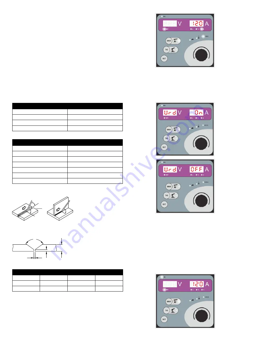
the v. r. d. function is on.
turn off the machine with the main switch. push and hold the mma button on
the control panel and turn the machine on with the main switch. hold the mma
button until a vrd – on or vrd – off sign appears, see the picture below. the
display will show the v.r.d. function status for a moment.
Welding in MMA method
a) With the machine disconnected from power supply connect the electrode hol-
der and grounding cable to clamps 1 and 2. choose the electrode’s polarity for
the particular electrode according to manufacture’s specifications.
b) connect the machine to power supply.
c) turn on the main switch (5).
d) Wait for the welding machine test to finish – all control lights and displays will
be on for several seconds.
e) switch the machine to the mma method with button 5.
f) set the welding current. set the desired value of the welding current with the
rotating selector (11). the value will show on display (14). at the same time the
control light in field 4 will be on showing the ampere value.
g) by pushing the set (7) button on the control panel we can switch the individual
functions one by one. We can select the function status and its value with the
rotating selector (11). if needed, we can adjust the settings of the hot start,
arc force and remote controls functions.


