


28
|
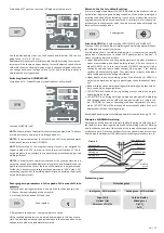
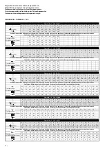
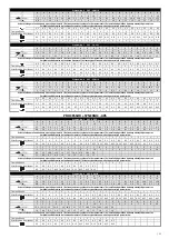
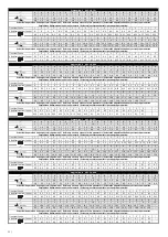
Principle of setting welding parameters
Guidance for setting welding current and voltage MIG / MAG corresponds to
the empirical relationship U
2
= 14 + 0.05 x I2. According to this relationship,
we can determine the necessary tension. When setting the voltage, it must be
taken into account when it falls under the welding load. The voltage drop is
about 4.8 V per 100 A.
The welding current is adjusted by adjusting the required welding current
for the selected welding voltage by increasing or decreasing the wire feeding
speed, or by fine-tuning the voltage until the welding arc is stable. To achie
-
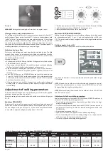
ve a good weld quality and optimum welding current setting, the distance
between the feed die and the material must be approximately 10 x Ø of the
welding wire (pic. 6). Drowning the die in the gas nozzle should not exceed
2 - 3 mm.
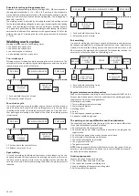
Welding work cycles
Welding machines work in four working cycles:
• continuous two-stroke time
• continuous four-stroke time
• spot welding two-stroke time
• pulse welding two/four -stroke time
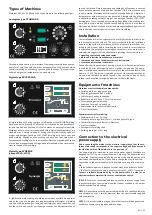
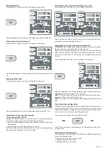
Two-stroke cycle
Welding process is started by only the pressing the switch of the torch. The
switch must always be held during the welding process and it can be inter
-
rupted releasing the switch of the torch.
PRE-GAS
WELDING PROCESS
POST-GAS
END OF THE
WELDING
PROCESS
START OF THE
WELDING
PROCESS
1
2
1 - Push and hold the switch of torch
2 - Release the switch of torch
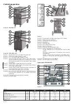
Four-stroke cycle
It is used to weld long, when the welder does not have to hold the switch of
the torch all the time. You will start the welding process in such a way. After
releasing of the switch, the welding process still goes on. Only after a fur
-
ther pressing and releasing of the switch of the torch, the welding process
is interrupted.
PRE-GAS
WELDING PROCESS
POST-GAS
END OF THE
WELDING
PROCESS
START OF THE
WELDING
PROCESS
1-2
3-4
1-2 Push and hold the switch of torch
3-4 Release the switch of torch
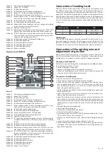
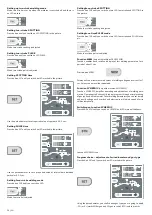
Spot welding
It is used for welding by individual short spots, whose length can be con
-
tinuously adjusted for required value. By pressing the switch on the torch,
the time circuit is started, which starts the welding process and after the
set time it turns off. After further pressing the button, the whole process is
repeated.
PRE-GAS
WELDING IN ADJUSTED TIME
POST-GAS
START OF THE
WELDING
PROCESS
1
END OF
THE WELDING
PROCESS
2
1 - Push and hold the switch of torch
2 - Release the switch of torch
Pulse welding
It is used for welding by short spots. Length of these spots and pauses can
be continuously adjusted. By pressing the switch of the torch, time circuit is
started, which starts the welding process and after certain time turns it off.
After set pause, the whole activity is repeated. To interrupt the function, it is
necessary to release the switch on the welding torch.
PRE-GAS
WELDING IN
ADJUSTED
TIME
POST-GAS
END OF
THE WELDING
PROCESS
START OF THE
WELDING PROCESS
1
2
PAUSE
WELDING IN
ADJUSTED
TIME
1 - Push and hold the switch of torch
2 - Release the switch of torch
Regular maintenance and inspections
Conduct the inspections according to the relevant Standard EN 60974-4. Be
-
fore any use of the apparatus, check the conditions of the welding and power
supply cables. Do not use damaged cables!
Visual inspections include:
1. Torch, welding current return clamp
2. Power supply network
3. Welding circuit
4. Covers
5. Controlling and indicating elements
6. Apparatus condition in general
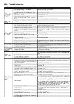
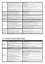
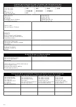
The pointing out of any difficulties and their elimination
The supply line is attributed with the cause of the most common difficulties.
In the case of breakdown, proceed as follows:
1. Check the value of the supply voltage
2. Check that the power cable is perfectly connected to the plug and the
supply switch
3. Check that the power fuses are not burned out or loose
4. Check whether the following are defective:
• The switch that supplies the machine
• The plug socket in the wall
• The generator switch
NOTE:
Given the required technical skills necessary for the repair of the ge
-
nerator, in case of breakdown we advise you to contact skilled personnel or
our technical service department.
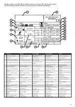
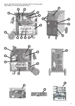
Ordering spare parts
For easy ordering of spare parts mention:
1. The order number and name of the part
2. The type of the machine or welding torch
3. Supply voltage and frequency from rating plate
4. Serial number of the machine
EN
Summary of Contents for 305
Page 22: ... 67 ...


