background image

62 

|

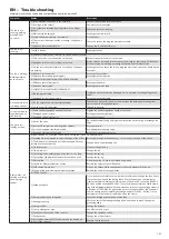
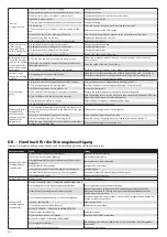
DE  -  Handbuch für die Störungsbeseitigung

Hinweis: Die Maschine können nur qualifizierte und entsprechend geschulte Mitarbeiter reparieren!

Defekt, Anzeichen

Grund

Lösung

Ventilator läuft nicht 

Schweißmaschine 

schweißt nicht.

1/ Ist die Maschine an das Netz geschaltet?

Maschine an das Netz schalten.

2/ Gibt es in der Steckdose Spannung?

Netzsteckdose überprüfen.

3/Ausgefallenes Draht aus der Klemmleiste des Steckers oder 

Steckdose?

Netzstecker oder -dose überprüfen.

4/ Hauptschalter ist beschädigt.

Hauptschalter austauschen.

5/ Ausgefallenes Kabel aus der Klemmleiste in der Maschine.

Kabel befestigen.

6/ Kleines Trafo bleibt ohne Spannung - Phase ausgefallen.

Steckdose, Stecker und Netzzuleitungskabel überprüfen.

7/ Steuerungstrafo defekt.

Steuerungstrafo austauschen.

Ventilator läuft nicht. Ventilator defekt.

Ventilator austauschen.
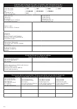
Ventilator läuft,

Schweißmaschine 

schweißt nicht.

A/ SCHÜTZ SCHALTET NICHT - VORSCHUB FUNKTIONIERT NICHT
1/ Steuerungsstecker des Brenners nicht angeschlossen.

Steuerungsstecker des Brenners anschließen.

2/Schalter oder Steuerungskabel im Brenner defekt.

Brenner frei schalten, zwei Kontakte für die Steuerung überbrücken Falls alle 

Maschinenfunktionen in Ordnung sind, den Schalter, das Koaxialkabel oder den 

ganzen Brenner austauschen.

3/ Am Kleintrafo keine Spannung - eine Phase ausgefallen.

Netzsicherung austauschen, Steckdose, Stecker und Zuleitungsnetzkabel überprüfen, 

Phasen am Schütz kontrollieren.

4/ Schütz - Spule defekt.

Schütz austauschen.

5/ Thermostaten defekt (siehe Schema).

Thermostaten austauschen.

B/ SCHÜTZ SCHALTET - VORSCHUB FUNKTIONIERT NICHT
1/Steuerungselektronik defekt.

Platte austauschen.

2/Vorschubmotor defekt - Kohlenstifte.

Vorschub - Kohlenstifte austauschen.

B/ SCHÜTZ SCHALTET, VORSCHUB FUNKTIONIERT

1/ Erdungskabel gebrochen.

Die Isolierung muss nicht beschädigt sein - es ist nicht sichtbar - das Erdungskabel 

austauschen.

2/ Koaxialkabel des Brenners defekt.

Koaxialkabel austauschen.
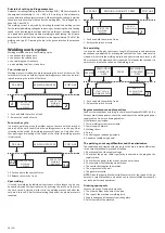
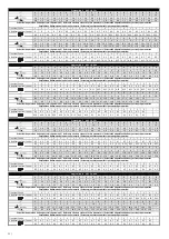
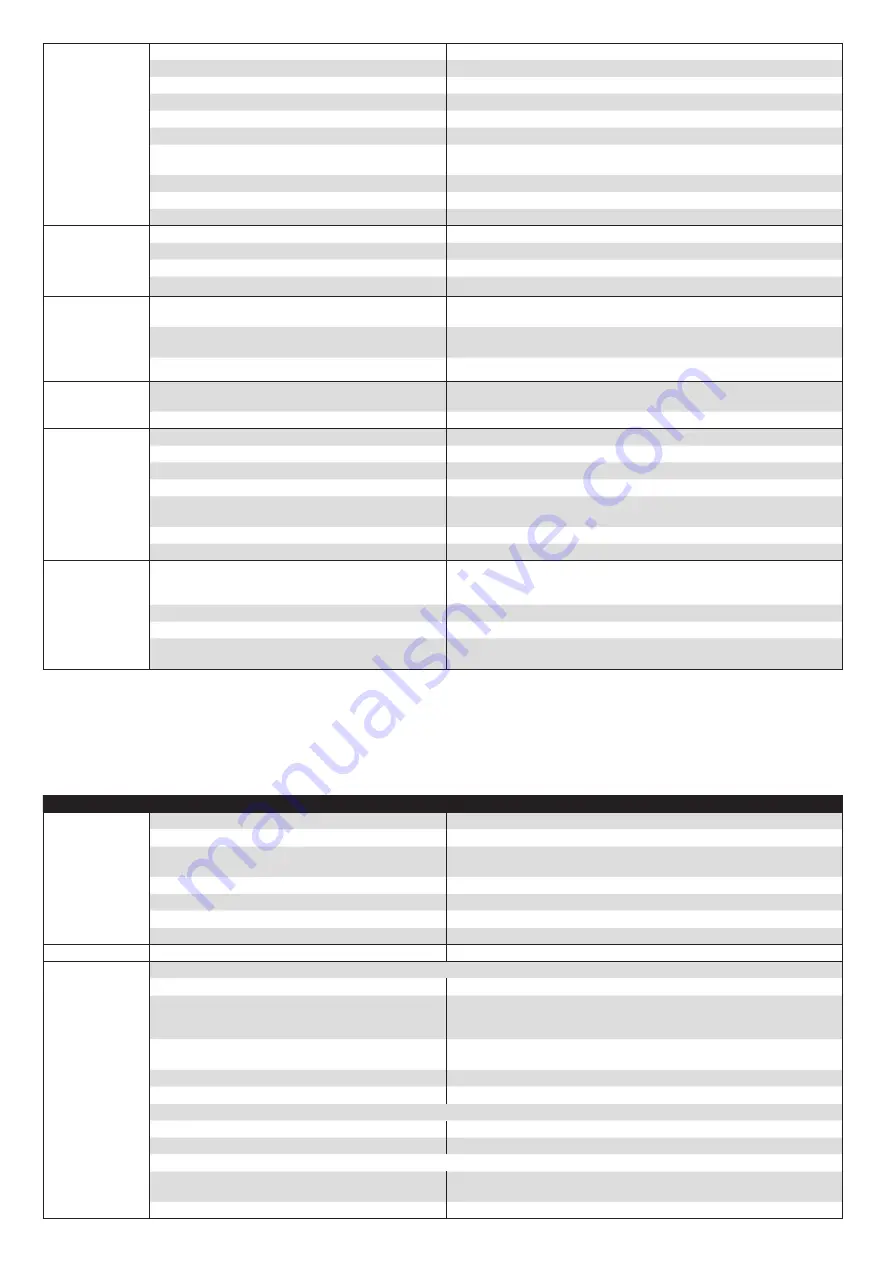
The wire 

is unregularly fed.

1/ Worn out sheave - the wire is slipping.

Change the sheave.

2/ Appropriate diameter of the sheave has not been used.

Change the sheave.

3/ Faulty motor - worn-out carbons or faulty retch.

Change the carbons, the retch or the whole motor.

4/ Rubbed-in upper sheave.

Change the upper pulley.

5/ The spring of the appropriate diameter has not been used. Change the spring.
6/ Dirty spring.

Clean the spring - the spring has to be cleaned every week.

7/ Thrust on the shift is too tight - the wire is being missha

-

pen.

Release the thrust of the shift sheave.

8/ Sheave for  some other  diameter of the wire.

Clap on the sheave which corresponds to the used diameter of the wire.

9/ Sheave of the feed is worn out.

Replace the sheave with a new one.

10 The spool of the wire is being too intensely braked.

Release the spool brake.

The el. transformer 

is making very 

strong grumbling 

noise, warming up 

and scorching.

1/ Damaged alteration switch of the currency.

Change the alteration switch.

2/ Damaged secondary rolling of the transformer.

Change the transformer.

3/ Damaged primary rolling of the transformer.

Change the transformer.

4/ Short circuit on the rectifier or the efferent.

Remove the cause of the short circuit.

Welding wire is red

-

-hot in the welding 

torch, on the sheave 

of the feed and the 

power cable is being 

warmed up.

1/ The spool or the wire is touching the machine case.

Flatten the misshapen parts of the spool in order that they do not touch the 

machine case.

2/ Metal dirt connect the body of the feed with the case of 

the welding machine.

Clean the space of the feed from all dirt.

3/ The rectifier is touching the case of the machine.

Avoid the contact of the body of the rectifier and the case of the machine.

Gas does not go 

through the welding 

machine.

1/ Clogged gas hose in the welding torch.

Make sure if the right inner diameter of the spring has been used, try to clap on

a different welding torch or change coaxial cable or the whole welding torch.

2/ The valve is without voltage.

Change the panel of controlling electronics.

Porous welding 

point.

1/ Gas is not on or the compressed gas cylinder is empty.

Turn gas on or connect a new full compressed gas cylinder.

2/ Too strong draught in the working place.

Increase the flow of the shielding/protective gas or avoid draught.

3/ Material is destroyed by rust, paint or oil.

Purify the material well.

4/ The orifice of the drawing die is dirty from the spatter.

Remove the spatter and spray the orifice with separating spray.

5/ The welding torch is too far from the material.

Hold the welding torch from the material in such a distance which equals 10 times 

bigger than the diameter of used welding wire.

6/ Too small or too big flow of the gas.

Adjust the flow of the gas on the appropriate values.

7/ Hose connections do not seal.

Check if all hose connections seal.

Welding wire forms

a loop between 

the sheaves and 

the opening of the 

capillary of the 

welding torch.

1/ The opening of drawing die (point of the welding torch) is 

too narrow, does not correspond to the diameter of the used 

welding wire.

Change the drawing die  and use the right one.

2/ Pressure on the flattening sheave is too big.

Release the flattening sheave of the feed.

3/ Dirty or damaged spring in the welding torch.

Clean the spring - the spring has to be cleaned every week or change it.

4/ The spring in the welding torch  is suitable for some other 

diameter of the welding wire.

Change the drawing die for a suitable one.

Summary of Contents for 305

Page 1: ...OJ NÁVOD NA OBSLUHU ZVÁRACÍ STROJ INSTRUCTION FOR USE WELDING MACHINE BEDIENUNGSANLEITUNG SCHWEIßGERÄTE INSTRUKCJA OBSŁUGI MASZYNA SPAWALNICZA MADE IN EU 3500 4100 305 405 STANDARD PROCESSOR STANDARD PROCESSOR SYNERGIC CZ SK EN DE PL ...

Page 2: ...d for welding of thin and thickness materials for wires used from 0 6 to 1 2 mm Standard equipment of ma chines can be found in chapter Equipment of welding machines Welding machines confirm to all European Union and Czech Republic standards and directives in force Contents ENGLISH INTRODUCTION 20 DESCRIPTION 20 TECHNICAL DATA 20 TYPES OF MACHINES 21 INSTALLATION 21 EQUIPMENT OF WELDING MACHINES 2...

Page 3: ...romagnetic problems in the work area In particular we suggest that you should avoid installing the system close to signalling control and telephone cables radio and television transmitters and receivers computers and control and measurement instruments security and protection instruments Persons fitted with pacemakers hearing aids and similar equipment must consult their doctor before going near a...

Page 4: ...sition 10 Switch 2 4 stroke 8 3 6 1 9B 2 7 4 5 13 20 14 15 16 17 19 18 21 11 12 Picture 2 Position 11 Terminal board of voltage supply for gas 42 V AC heating Position 12 Supply cable with connection Position 13 Loading tube of EURO connector Position 14 Wire feeder Position 15 Loading bowden Position 16 Wire spool holder with brake Position 17 Adaptor of wire spool Position 18 Automatic electroma...

Page 5: ...d on Connection of welding torch With the machine disconnected from the supply connect welding torch into EURO connector pic 1A B position 7 and tighten well the cap nut Connect the grounding cable to the grounding quick coupler pic 1A B po sition 9A B and tighten the ground quick coupler At the machines series 305 405 appoint the outlet as shown in Table 3 or refer to the Recommen ded welding par...

Page 6: ...main welding parameters of welding voltage and speed of wire shift is carried out with a potentiometer of wire speed pic 1A B pos 5 and a voltage switch pic 1A B pos 2 3 You shall always allocate speed of wire shift to adjusted voltage switch position 1 20 1 40 2 1 3 1 Both potentiometers switched off function switched off normal welding 2 Left Potentiometer Active Right Off Set the spot time 3 Bo...

Page 7: ...Before adjusting the approaching speed of the wire switch off the start time of the wire speed shift set the value 0 Adjustment of the approaching speed the wire outlet is possible only when the function of the start time of wire speed is switched off it means you have to set the value 0 according to the description in the previous chapter Press the button SET until the LED is on marked in the pic...

Page 8: ...ime PULSE mode Press button FNC until you switch on two LED four stroke and PULSE in the pic Mode four stroke pulse is adjusted Function MEM only with machines PROCESSOR Function enables back recall and display of last welding parameters for a period of about 7 sec Press button MEM Display will show last measured values of welding voltage and current for 7 sec Values can be recalled repeatedly Fun...

Page 9: ...reading In such a way it is possible to return single parameters which have been stored A total return of all the pre ad justed values to the values set up by the producer can be done through the function factory configuration Keep together Function LOGIC only with machines PROCESSOR and SYNERGIC Function LOGIC includes a file of simplifying and clarifying points which pre sent adjusted and curren...

Page 10: ...e torch the time circuit is started which starts the welding process and after the set time it turns off After further pressing the button the whole process is repeated PRE GAS WELDING IN ADJUSTED TIME POST GAS START OF THE WELDING PROCESS 1 END OF THE WELDING PROCESS 2 1 Push and hold the switch of torch 2 Release the switch of torch Pulse welding It is used for welding by short spots Length of t...

Page 11: ...ětí Menovité napájacie napätie Supply voltage Nennspeisespannung und Frequenz Napięcie nominalne i frekwencja zasilania 9 Třída izolace Trieda izolácie Insulation class Isolierungsklasse Klasa izolacji 10 Krytí Krytie Protection degree Schutzart Stopień ochrony 11 Chlazení ventilátorem Chladenie ventilátorom Air cooled Ventilatorkühlung Chłodzenie wentylatorem 12 Svařovací poloautomat MIG MAG Zvár...

Page 12: ...sory values of other parameters Orientačné odporúčané hodnoty ostatných parametrov Empfohlene Richtwerte der anderen Parameter Orientacyjne zalecane wartości pozostałych parametrów 0 5 0 5 0 5 0 5 0 5 0 5 0 5 0 5 0 5 0 5 0 5 0 5 0 5 0 5 0 5 0 5 0 5 0 5 0 5 0 5 Tlumivka Choke 1 1 1 1 1 1 1 1 1 1 1 1 1 2 2 2 2 2 2 2 Výlet Starting from feeder 0 3 0 3 0 3 0 3 0 3 0 3 0 3 0 3 0 3 0 3 0 6 0 6 0 6 0 6 0...

Page 13: ... 0 15 1 1 1 1 1 1 1 1 1 1 1 1 1 1 1 1 1 1 1 1 PROCESSOR SYNERGIC 405 Program No 3 405 0 8 CO2 A A A A A A A A A A B B B B B B B B B B 1 2 3 4 5 6 7 8 9 10 1 2 3 4 5 6 7 8 9 10 2 7 2 8 3 0 3 1 3 3 3 3 3 4 3 5 3 7 3 7 3 7 3 8 3 8 4 1 4 6 5 5 6 2 7 0 7 7 8 5 0 8 1 0 1 2 1 5 1 8 2 0 2 5 3 0 3 1 3 3 3 4 3 6 3 8 4 0 4 5 5 0 5 5 6 0 6 5 7 0 Orientační doporučené hodnoty ostatních parametrů Reference advi...

Page 14: ... 0 5 0 5 0 20 0 20 0 20 0 20 0 20 0 20 0 15 0 15 0 15 0 1 0 1 0 1 0 1 0 1 0 1 0 1 0 1 0 1 Program No 7 405 1 2 CO2 A A A A A A A A A A B B B B B B B B B B 1 2 3 4 5 6 7 8 9 10 1 2 3 4 5 6 7 8 9 10 1 7 2 4 2 8 3 5 3 5 3 5 3 7 3 7 3 8 3 9 3 9 4 0 4 1 4 3 4 3 4 6 5 3 5 3 5 7 5 8 1 0 1 2 1 5 1 8 2 0 2 5 3 0 3 2 3 5 4 0 4 5 4 8 5 0 5 3 5 5 6 0 6 5 7 0 7 5 8 0 Orientační doporučené hodnoty ostatních par...

Page 15: ...ales of wire shift speed STANDARD m min Tabela porównująca skale szybkości podajnika drutów maszyn STANDARD m min Stupnice potenciometru Scale of potentiometer Skala potencjometru Potentiometer Skala Skala potencjometru 1 2 3 4 5 6 7 8 9 10 11 Orientační hodnoty v m min Reference values in m min Wartości orientacyjne w m min Richtwerte in m Min Wartości orientacyjne w m min 4 5 8 11 5 15 18 20 5 2...

Page 16: ...54 Elektrotechnické schéma Elektrotechnické schéma Electrical diagram Schema Schemat elektrotechniczny 305 405 3500 4100 STANDARD 305 405 PROCESSOR SYNERGIC ...

Page 17: ... 55 Seznam náhradních dílů Zoznam náhradných dielov List of spare parts Ersatzteilliste Lista części zamiennych maszyn 15 4 16 21 20 26 11 14 7 2 19 12 9 5 3 4 23 1 22 13 17 18 8 6 25 10 24 ...

Page 18: ...ra Sunon Fan border NT Sunon 305 405 30512 13 Redukce cívky adaptér AEK Redukcia cievky adaptér AEK Adaptor AEK 30096 14 Rychlo zásuvka panel 35 50 šestihran Rychlo zásuvka panel 35 50 šestihran Gladhand socker panel 35 50 30423 15 Stykač 32 A Stykač 32 A Contactor 32 A 31000 16 Termostat 130 C EAW 229 Termostat 130 C EAW 229 Thermostat 130 C EAW 229 31088 17 Tlačítko 3 A červené Tlačítko 3 A červ...

Page 19: ...ard The gas is still leaking by torch 1 Dirt on the valve Do the disassembly and purifying or exerts tension on the spring or exchange the valve 2 Incorrectly set pressure reducing valve cylinder Set the pressure 3 It is used inappropriate throttle valve Use appropriate reducing valve 4 Damaged electromagnetic valve Exchange electromagnetic valve Badly welds it s sticking scorching shaking large s...

Page 20: ...ter of the wire 9 Sheave of the feed is worn out Replace the sheave with a new one 10 The spool of the wire is being too intensely braked Release the spool brake The el transformer is making very strong grumbling noise warming up and scorching 1 Damaged alteration switch of the currency Change the alteration switch 2 Damaged secondary rolling of the transformer Change the transformer 3 Damaged pri...

Page 21: ...t Záručnýlist Warrantycertificate Garantieschein Karta Gwarancyjna Datum prodeje Dátum predaja Date of sale Verkaufsdatum Data sprzedaży Razítko a podpis prodejce Pečiatka a podpis predajca Stamp and signature of seller Stempel und Unterschrift des Verkäufers Pieczątka i podpis sprzedawcy Záznam o provedeném servisním zákroku Záznam o prevedenom servisnom zákroku Repair note Eintrag über durchgefü...

Page 22: ... 67 ...

Page 23: ...e si vyhrazuje právo na změnu Výrobca si vyhradzuje právo na zmenu The producer reserves the right to modification Hersteller behaltet uns vor Recht für Änderung Producent zastrzega sobie prawo do zmian 09 2019 ...

Reviews: