

22
|
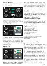
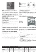
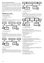
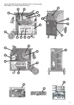
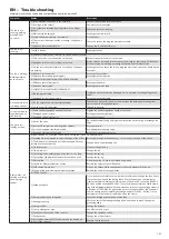
Control apparatus
1
2
3
10
4
8
9A
6
7
5
Picture 1A - TYPES 305, 405
Picture 1B - TYPES 3500, 4100
Position 1 Supply switch. In the „O“ position the welder is off.
Position 2 10-positional voltage changeover switch.
Position 3 2- or 4- positional voltage changeover switch.
Position 4 Thermostat yellow signal light. When this light comes it means
that the overheat cut-off has come on, because the work cycle
limit has been exceeded. Wait for a few minutes before starting
to weld again.
Position 5 Potentiometer of speed adjustment of the wire feed.
Position 6 Switch of spot welding function with potentiometer of adjus
-
tment of spot welding length.
Position 7 Switch of PAUSE function with potentiometer of adjustment of
pause length between each spots - slow pulses.
Position 8 EURO connector of welding burner connection.
Position 9A Choke outlets for earth cable connection. Type 305/405 is used
to set the dynamic properties of the welding current source
(see Table 3).
Position 9B Quickcoupling for grounding cable connection.
Position 10 Switch 2/4-stroke
8
3
6
1
9B
2
7
4
5
13
20
14
15
16
17
19
18
21
11
12
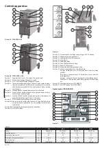
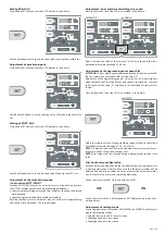
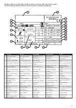
Picture 2
Position 11 Terminal board of voltage supply for gas 42 V AC heating.
Position 12 Supply cable with connection.
Position 13 Loading tube of EURO connector.
Position 14 Wire feeder.
Position 15 Loading bowden.
Position 16 Wire spool holder with brake.
Position 17 Adaptor of wire spool.
Position 18 Automatic electromagnetic gas valve.
Position 19 Setting of potentiometers: (only Standard)
Pre-gas - setting the time of pre-gas before start of welding
process.
Burning out - setting the time of burning out of wire after the
welding process
Post-gas - setting the time of post-gas after the welding process
Wire let-out - the wire feed speed before ignition of the welding
arc
Position 20 Wire feed button (only STANDARD).
Position 21 GAS TEST button (only STANDARD).
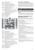
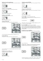
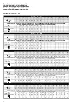
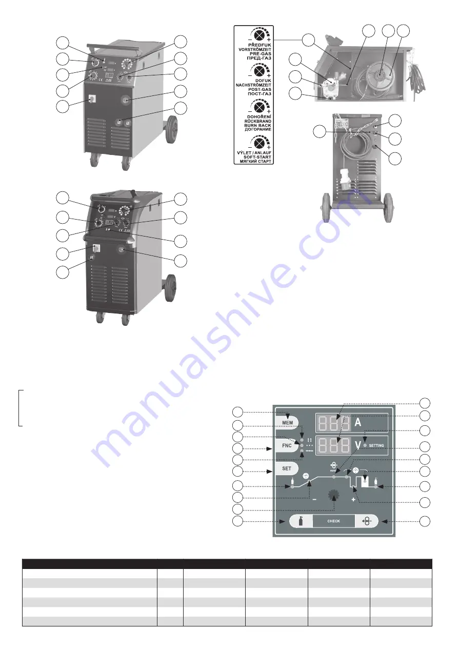
Digital control PROCESSOR
19
18
17
16
15
14
13
10
9
8
7
6
5
3
4
1
2
11
12
Picture 3
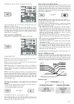
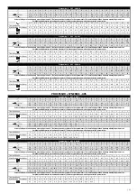
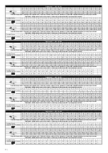
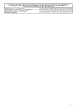
Table 2
305
405
3500
4100
I Max
[ A ]
280 (30 %)
350 (30 %)
280 (40 %)
350 (35 %)
Installed power
[ kVA ]
9.9
13.5
7.8
11
Protection slow, char. D
[ A ]
25
25
25
25
Diameter of input connection
[ mm
2
]
4 x 2.5
4 x 2.5
4 x 2.5
4 x 2.5
Earth cable-cut
[ mm
2
]
35
70
35
50
Welding torch
KTB 25/36
KTB 36
KTB 25/36
KTB 36
EN
Only S
TAND
ARD
Summary of Contents for 305
Page 22: ... 67 ...


