


|
23
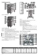
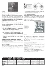
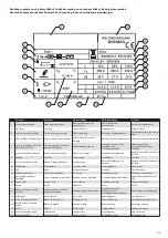
Position 1 Potentiometer setting parameters.
Position 2 Button TEST OF GASES.
Position 3 LED illustrating pre-gas.
Position 4 LED illustrating start of speed of welding wire.
Position 5 Button SET - it allows choosing setting parameters.
Position 6 LED illustrates switching on of pulse function.
Position 7 Button welding mode - it allows switching on and off of two
-
-time and four-time modes, spot and pulse welding.
Position 8 LED illustrating spot welding mode.
Position 9 LED illustrating four-time welding mode.
Position 10 Button MEM allows loading of values of voltage and welding
current which were measured last time.
Position 11 Display of welding current.
Position 12 Display showing welding pressure and values with LED SETTING
light up. They are values of speed of wire feeder, pre-gas etc.
Position 13 LED SETTING which is on only when parameters are shown spe
-
ed of wire feeder, start of wire, pre-gas and post-gas, spot time
and pulse time, burning out of wire.
Position 14 LED illustrating speed of shifting of welding wire.
Position 15 LED illustrating spot time.
Position 16 LED illustrating burnt out time.
Position 17 LED illustrating post-gas time
Position 18 LED illustrating pulse time.
Position 19 Button wire feeder.
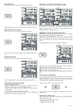
Digital control SYNERGIC
11
10
9
8
7
6
5
3
1
2
4
13
14
15
17
18
19
20
21
22
23
16 12
Picture 4
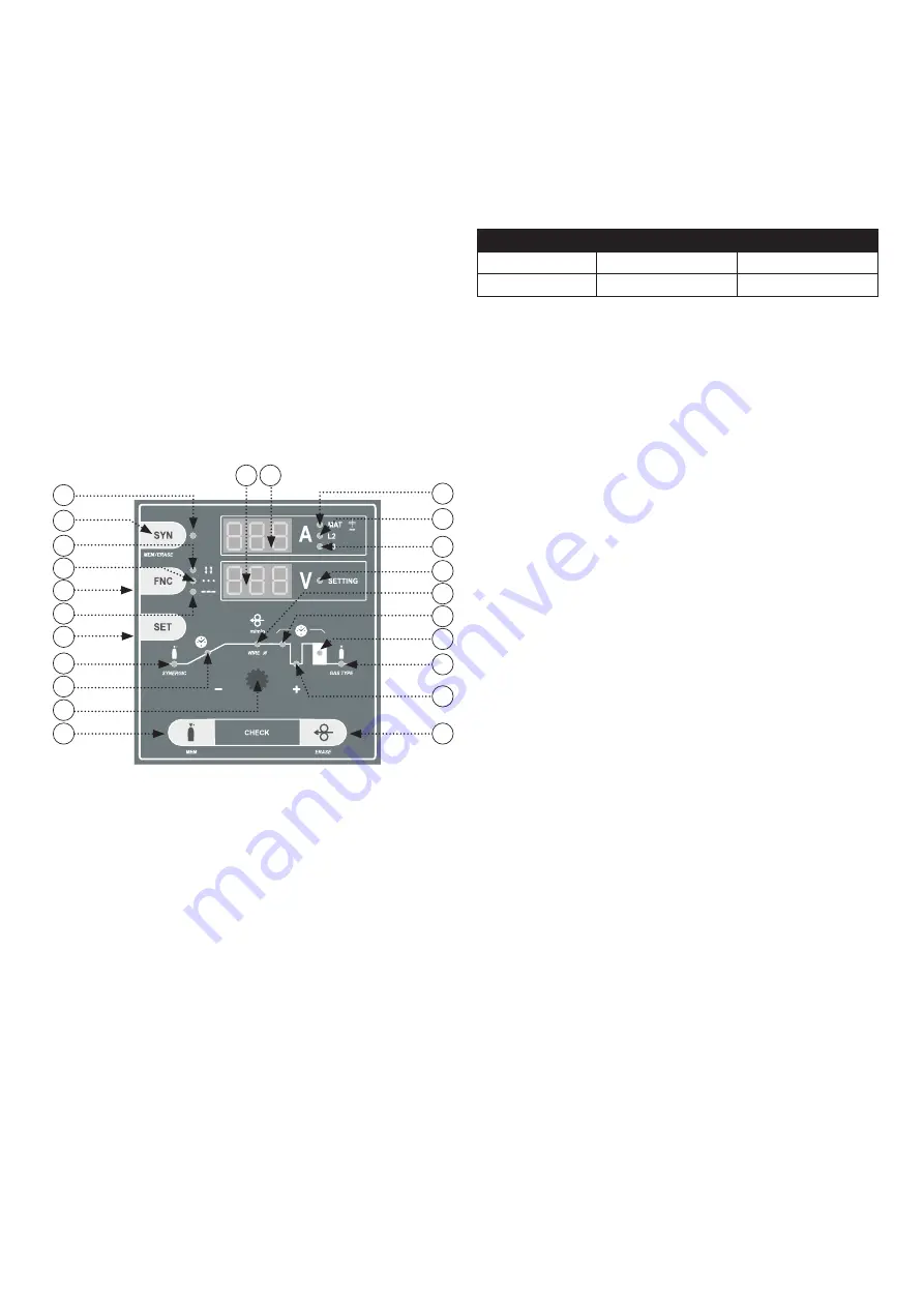
Position 1 Potentiometer setting parameters.
Position 2 Button TEST OF GASES.
Position 3 LED illustrating pre-gas.
Position 4 LED illustrating start of speed of welding wire.
Position 5 Button SET - it allows choosing setting parameters.
Position 6 LED illustrates switching on of pulse function.
Position 7 Button welding mode - it allows switching on and off of two
-
-time and four-time modes, spot and pulse welding.
Position 8 LED illustrating spot welding mode.
Position 9 LED illustrating four-time welding mode.
Position 10 Switch of synergic function - SYN on and off.
Position 11 LED signalling switching synergic function on.
Position 12 Display of welding current.
Position 13 LED signalling approximate power values of welding material
on display. When diode is off display shows value of welding
current.
Position 14 LED shows which outlet of inductor should be used.
Position 15 LED shows which outlet of inductor should be used.
Position 16 Display shows welding current. When LED “SETTING” is on, dis
-
play shows values of wire feeder speed, pre-gas, post-gas etc.
Position 17 LED SETTING which is on only when parameters are shown:
speed of wire feeder, start of wire, pre-gas and post-gas, spot
time and pulse time, burning out of wire.
Position 18 LED illustrating speed of shifting of welding wire.
Position 19 LED illustrating spot time.
Position 20 LED illustrating burnt out time.
Position 21 LED illustrating post-gas time.
Position 22 LED illustrating pulse time.
Position 23 Button for wire lead on.
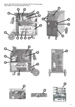
Connection of welding torch
With the machine disconnected from the supply, connect welding torch
into EURO connector (pic. 1A/B, position 7) and tighten well the cap nut.
Connect the grounding cable to the grounding quick coupler (pic. 1A/B, po
-
sition 9A/B) and tighten the ground quick coupler. At the machines series
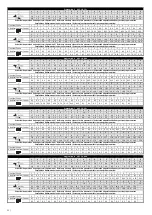
305/405, appoint the outlet as shown in Table 3 or refer to the „Recommen
-
ded welding parameter setting“ table. Welding torch and earth cable should
be as short as possible, close to each other and positioned at the floor level
or close to it.
Table 3
Induction outlet
305
405
L1
30 A - 120 A
30 A - 180 A
L2
80 A - 250 A
140 A - 350 A
Welding part
The part to be welded must always be connected to earth in order to re
-
duce electromagnetic emission. Much attention must be afforded so that
the earth connection of the part to be welded does not increase the risk
of accident to the user or the risk of damage to other electric equipment.
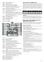
Connection of the welding wire and
adjustment of gas flow
Before connecting the welding wire, it is necessary to check the wire feed
rolls if they correspond to the profile of roll groove. When using the steel
welding wire, it is necessary to use the roll with V-shaped roll groove.
Changing of wire feed roll
Rolls are two-grooved. These grooves are designed for two different diame
-
ter of the wire (e.g. 0.8 and 1.0 mm).
• lift the holding-down mechanism
• screw out the locking plastic screw and take out the roll
• if there is a suitable groove on the roll, turn the roll and put it back on the
shaft and secure it with a plastic locking screw
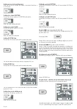
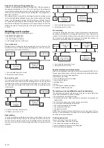
Connection of welding wire
• take off the side cover of wire container
• put on the wire spool onto the holder into the container
• cut off the end of the wire fastened to the edge of the roller and lead it
into the loading bowden (pic. 2, pos. 15), then through the roll of feed
into the loading tube (pic. 2, pos. 13) 10 cm at least, check if the wire
leads through the right feed groove
• tilt the holding-down roll down and return the holding-down mechanism
into the vertical level
• adjust the nut pressure of thrust to secure the wire feed without pro
-
blems and deformation by too much thrust
• adjust the welding wire coil brake so that the coil turns freely when the
feed mechanism is switched off. Too tightened brake greatly straps the
feed mechanism and wire may slip in the pulleys and misfeed. The brake
adjusting screw is located under the plastic screw of the bobbin holder
(pic. 5).
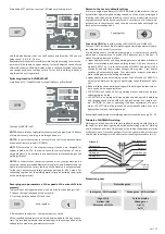
• dismount the gas tip of welding torch
• unscrew the flow drawing tip
• connect the socket plug into the network
• turn on the main switch into pos. 1
• press the wire feed button for STANDARD inside the machine (pic. 2, pos.
20), for PROC./SYN. on the control panel
• after the run of wire from the torch, screw the flow drawing tie and gas
tube
• connect the protective gas to the gas valve (pic. 2, pos. 18)
• before welding use anti-spatter spray in the space of gas tube and flow
drawing tie; in that way you prevent adherence of metal spatter and pro
-
long the life of gas tube
EN
Summary of Contents for 305
Page 22: ... 67 ...


