24
|
Picture 5
WARNING!
During wire threading don’t aim the torch against eyes!
Changes when useing aluminium wire
For welding with aluminium wire it is necessary to use a special roll with „U“
profile (chapter “Spare parts of wire feed”). In order to avoid problems with
„ruffle“ of wire, it is necessary to use wire in diameter min. 1.0 mm from
alloys AIMg3 or AIMg5. Wires from alloys A199.5 or AlSi5 are too soft and
can easily cause problems with feed. For welding of aluminium it is nece
-
ssary to equip the torch with teflone bovden and special flow drawing tie. As
shielding atmosphere it is necessary to use pure Argon.
Adjustment of gas flow
Electric arc and welding pool must be perfectly protected by gas. Too little
amount of gas cannot create necessary shielding atmosphere and on the
contrary, too big amount of gas entrains air into electric arc, which makes
the weld imperfectly protected.
Proceed as follows:
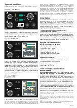
• fix the gas tube with the filter on the inlet of the gas valve on the back side
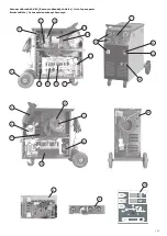
of the machine (pic. 2, pos. 18)
• if you use gas carbon dioxide, it is suitable to plug in gas heating (during
the flow less than 6 litres/min the heating is not necessary)
• plug in the cable of heating into the socket (pic. 2, pos. 11) on the machi
-
ne and into the connector at cylinder pressure regulator, polarity is not
important
• press GAS TEST button - for STANDARD from the rear of the machine (pic.
2, pos. 21), for PROC./SYN. on the control panel. Turn adjustment screw
on the bottom side of pressure valve until flow indicator shows required
flow, then release the button
• if the machine was not used for a longer time, or after entire change of
welding torch, it is recommended to blow ways by fresh gas before you
start welding
Adjustment of welding parameters
Adjusted parameters depend on used protective gas, wire diameter, applied
wire type, size and position of a weld etc.
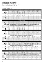
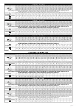
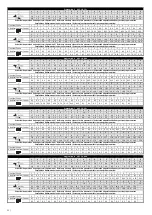
Reference setting of wire speed and switch positions can be found in pages
50 - 53.
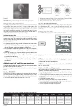
Machines STANDARD
Adjustment of main welding parameters of welding voltage and speed of
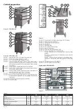
wire shift is carried out with a potentiometer of wire speed (pic. 1A/B, pos.
5) and a voltage switch (pic. 1A/B, pos. 2, 3). You shall always allocate speed
of wire shift to adjusted voltage (switch position 1-20/1-40).
2
1
3
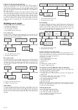
1 - Both potentiometers switched off - function switched off, normal welding
2 - Left Potentiometer Active / Right Off - Set the spot time
3 - Both potentiometers active - set the pulse time
Machines PROCESSOR/SYNERGIC
Setting of main welding parameters of welding voltage and wire feed speed
by a potentiometer (pic. 3, 4, pos. 1) and a voltage switch (pic. 1A/B, pos.
2, 3). The wire speed is always assigned to the set voltage (switch position
1-20/1-40).
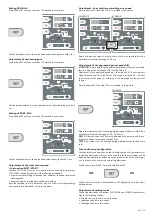
Setting speed of wire shift
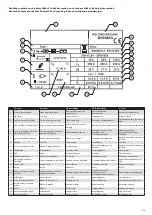
Press button SET until you switch on LED marked in the picture.
Use the potentiometer to set up required value of shift speed within range
1-20 m/min
NOTE 1:
Speed of wire shift can also be adjusted and changed during wel
-
ding. Either a potentiometer or a remote control UP/DOWN can be used.
During welding (turning the potentiometer).
NOTE 2:
Bottom display shows speed of wire shift only if red LED SETTING
and LED “m/min” are on.
Adjustment of other welding parameters
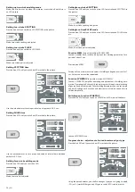
Controlling electronics of machines PROCESSOR and SYNERGIC enables ad
-
justment of the following welding parameters:
• Time duration of pre-gas (time of protective gas blow before the begi
-
nning of welding process).
• Time of start of wire shift speed - function SOFT START (time of start from
minimum shift speed up to value of adjusted welding wire speed, only
PROCESSOR).
• Approaching wire speed (table 4).
• Speed of wire shift m/min (speed of wire shift during welding).
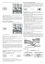
• Time of switching off interval of welding voltage on arc opposite wire
shift: „burning out“ of wire towards the torch top.
• Time of post-gas after finishing welding process.
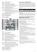
Table 4 - Range of value settings -
Machines PROCESSOR and SYNERGIC
the duration
of the pre-gas
approach
speed
wire feed rate
rise time
wire feed
speed
point time
lag time
burn out
post-gas time
(s)
(m/min)
(s)
(m/min)
(s)
(s)
(s)
(s)
PROCESSOR
305, 405, 3500, 4100
0 - 3
-
0 - 5
1 - 20
0.5 - 5
0.2 - 2
0.0 - 0.99
0.1 - 10
SYNERGIC
305, 405
0 - 3
0.5 - 20
-
1 - 20
0.5 - 5
0,2 - 2
0.0 - 0.99
0.1 - 10
EN
Summary of Contents for 305
Page 22: ... 67 ...


