|
27
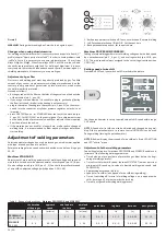
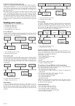
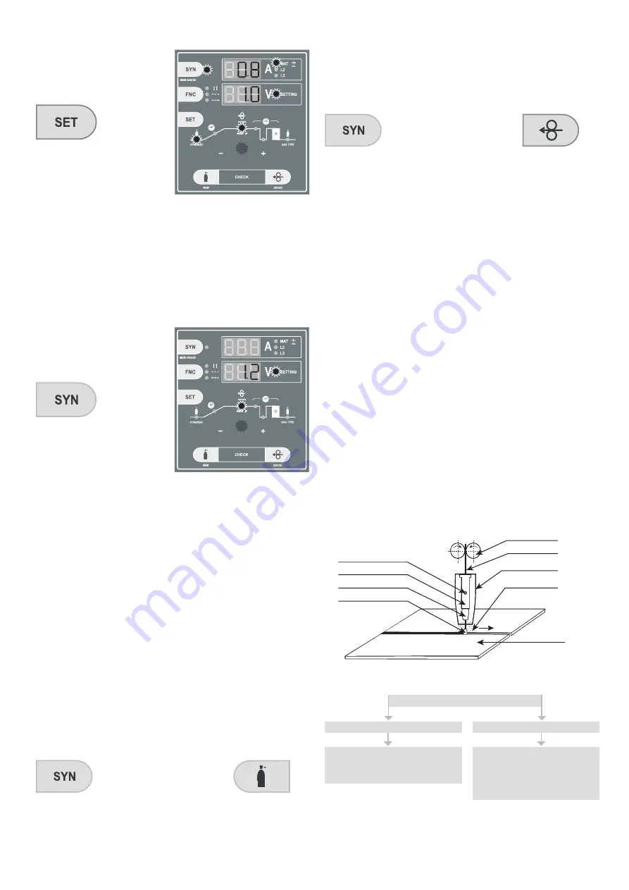
Press button SET until you switch on LED diode marked in picture.
Use the potentiometer, thus you shall choose wire diameter SG2 you are
going to use - 0.6 - 0.8 - 1.0 mm.
Approximate thickness of material possible to weld according to current ad
-
justment will be shown on upper display. Currently adjusted speed of wire
shift will be shown on bottom display, which is changed automatically when
you change positions of voltage switch. Fall or rise in welding capacity is
adjustted with a voltage switch.
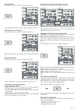
Switching function SYNERGIC off
Press button SYN. Diode SYN and material thickness will switch off.
Function SYNERGIC is off.
NOTE 1:
Shown values of material thickness are only approximate. Thickness
of material can vary according to welding position etc.
NOTE 2:
To correct parameter for wire shift, you shall use a potentiometer
or buttons of remote control UP/DOWN.
NOTE 3:
Parameters of the program synergic function are designed for
copper coated wire SG2. In order to reach the correct function of the sy
-
nergic programs, it is necessary to use quality wire, protective wire, gas and
welding material.
NOTE 4:
In order to reach the correct function of the synergic machine it is
necessary to keep prescribed diameters of cables to wire diameters and the
right die otherwise the correct function of the machine is not guaranteed.
Further on, it is necessary to secure quality power supply – 400 V, max. ± 5%,
connecting to ground of the welding material (use an earthing clip directly
on the welding material).
Recorging own parameters of the speed of the wire shift into
memory
The function of storing parameters is on only if the function synergic is on.
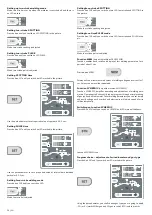
1. Choose the required speed of the wire shift.
2. Press and hold the button SYN and then.
Keep together
3. Release both the buttons - new parameters are stored.
All the required parameters can be stored and rewritten in this way as nece
-
ssary. The recorded parameter is adjusted always in the same position of the
voltage switch when the parameter was stored.
Return to the factory default settings
A return to original parameters SYNERGIC adjusted by the producer is done
by the follow-up pressing and holding the button SYN and then pressing and
releasing the button of wire threading. In such a way it is possible to return
single parameters which have been stored. A total return of all the pre-ad
-
justed values to the values set up by the producer can be done through the
function factory configuration.
Keep together
Function LOGIC
(only with machines PROCESSOR and SYNERGIC)
Function LOGIC includes a file of simplifying and clarifying points which pre
-
sent adjusted and currently set values.
If two displays show a few different parameters, it is necessary to simplify
presentation of parameters. Function LOGIC operates just in this way - it
makes everything clear and distinct:
• Upper display switches on during welding process only when electronics
makes measurements and shows welding current A (in case there is no
mode SYNERGIC on. In case there is mode SYNERGIC on display is lit up
constantly and only shown values change). After approx. 7 sec. display
switches off automatically again. Thus electronics increases orientation
while reading parameters during adjustment.
• Upper display shows only welding current. When function SYNERGIC is
on (only with machines Synergic), upper display shows thickness of mate
-
rial.
• Bottom display shows welding voltage while welding and other values -
time, speed etc. during adjustment.
• LED SETTING will switch off during welding process only when a digital
voltampermeter is used.
• LED SETTING is on during welding only when operating staff is adjusting
and changing speed of wire shift with a potentiometer or a remote con
-
trol UP/DOWN. As soon as operating staff stops adjustment of a para
-
meter, LED SETTING will be switched off automatically within 3 sec. and
display shows value of welding voltage.
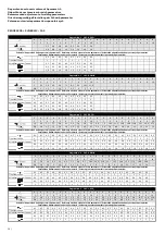
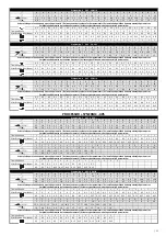
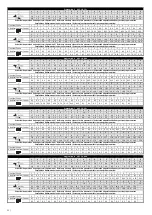
Recommended adjustment of welding parameters see charts on pg. 50 - 53.
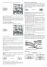
Principle of MIG/MAG welding
Welding wire is lead from the roller into the flow drawing tie with the use of
the feed. Arc joins thawing wire electrode with welding material. Welding
wire functions as a carrier of the arc and as the source of additional material
at the same time. Protective gas flows from the spacer which protects arc
and the whole weld against the effects of surrounding atmosphere (pic. 6).
Gas opening
Tip holder
Welding tip
Welding arc
Wire feeder rolls
Welding wire
Nas nosle
Protection gas
Welding
piece
Picture 6
Protection gases
Protective gases
Inert gases - MIG method
Active gases - MIG method
Argon (Ar)
Helium (He)
Mixtures of He/Ar
Carbon dioxide
Mixed gases
Ar/CO
2
Ar/O
2
EN
Summary of Contents for 305
Page 22: ... 67 ...


