www.gastron.com
18
_
19
5. Installation
GTD-3000TxW
Instruction Manual
6. Detector Operation Flow
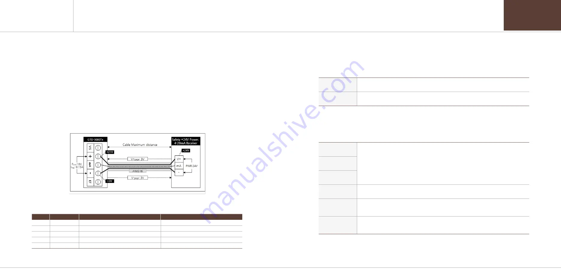
5.5. Installation Cable Length
[Figure 12. Calculation of GTD-3000TxW Installation Cable Length]
■ The maximum length between GTD-3000TxW and power supply is decided by wire specification.
■ Max. Installation Length = VMAXDROP ÷ IMAX ÷ WIRER/m ÷ 2
·VMAXDROP: Maximum Power Loop Voltage Drop (=Power Supply voltage
- min operating voltage)
·IMAX : Max. Current of GTD-3000TxW
·WIRER/m: The resistance of the wire (ohms/meter value available in wire manufacturer's specification data sheet)
■ Example of installation lengths using 24 V power supply and 16 AWG is as follows.
·GTD-3000TxW minimum operating voltage = 18 Vdc
·VMAXDROP = 24 - 18 = 6V
·IMAX = 0.23A(230mA)
·6 / 0.23 / 0.01318 / 2 = 989.641m = 990m
[Table 7. GTD- 3000TxW Power Cable Installation Length]
AWG
mm
2
COPPER RESISTANCE(ohms/m)
METERS
12
3.31
0.00521
2504
14
2.08
0.00828
1575
16
1.31
0.01318
990
18
0.82
0.02095
623
20
0.518
0.0333
623
■ Power cable installation for each cable type is as shown in the table below.
6.1. Initial Operation Status (Power On)
■ After wiring to power terminal at the top of Main PCB board then supply power, the following contents are displayed
on LCD. Approx. 30 m of stabilization of time is needed from the initial supply of operation power and it starts to operate
normally after sufficient stabilization.
GTD-3000
[Ver X.XX]
- When the power turns on, model name is displayed on the first row and firmware version of
the detector is displayed on the second row of LCD.
** SELFTEST **
[>>>>>>> 0179]
- Self test is performed for 3 min (30 min for O2 set-up), '>' symbol in the second row shows the progres
[ COMB.]
[ 0]%LEL
- It runs as below when it is normal and in gas measuring mode.
- Gas name is displayed on the first row and the current measurement and unit is displayed on the
-
second row.
※ During HART network, '*' is displayed on the left of the first row.
※ ENG. When the mode is on, '<' is displayed on the left of the second row.
※ During 485 network, '*' is displayed on the right of the first row.
* [ COMB.]
< 0]%LEL
[ COMB.]*A01
[ 0]%LEL
[ COMB.]
[ OVER]%LEL
- When gas measurement larger than 10% of set high scale value, "OVER" displays in 1 sec interval.
- At this time, 4~20 mA runs as 22 mA.
[ COMB.]
[ UNDER]%LEL
- When gas measurement smaller than -10%, "UNDER" displays in 1 sec interval and 4~20 mA runs at 2 mA.
※ The following function only runs when UNDER is on.
[FAULT 08]
SENSOR HUNTING
- When trouble occurs in the device, it displays fault number and message.
- At this time, 4~20 mA runs at 0 mA. (2 mA when HART is used.)
- Fault #-8 on the left is a mode that is displayed when there is repeated hunting error from the sensor.
6.2. Measuring Mode
■ After power on, when there is no error from "SELF TEST", it automatically enters Measuring Mode.


